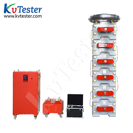
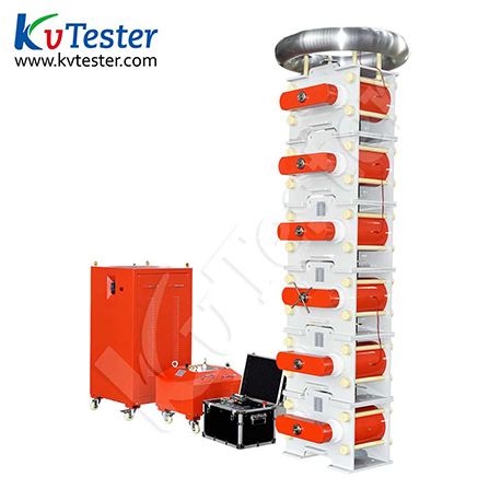
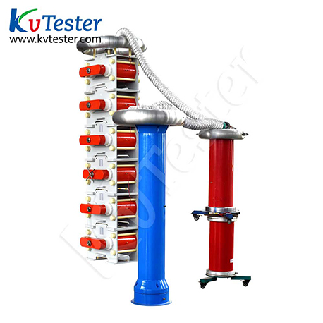
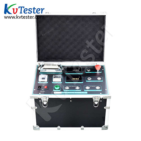
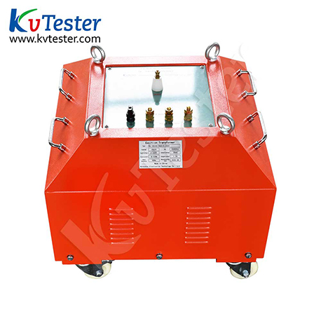
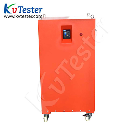
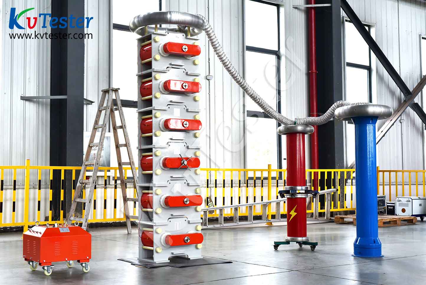
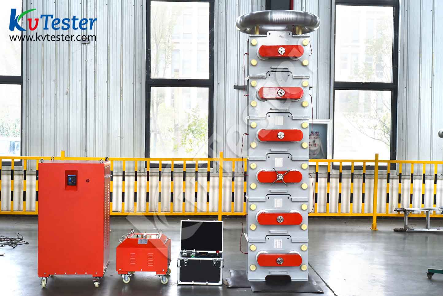
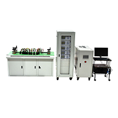
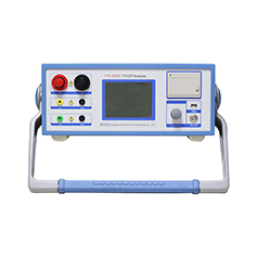
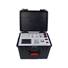
1. The required power capacity is greatly reduced. Series resonant power supply generates high voltage and high current through resonance between resonant reactor and the tested capacitor. In the entire system, the power supply only needs to provide the active consumption part of the system. Therefore, the required power supply for the experiment is only 1/Q of the test capacity.
2. The weight and volume of the equipment have been greatly reduced. In a series resonant power supply, not only is the bulky high-power voltage regulating device and ordinary high-power power frequency test transformer eliminated, but the resonant excitation power supply only requires 1/Q of the test capacity, greatly reducing the weight and volume of the system, usually 1/10 of ordinary test devices.
3. Improve the waveform of the output voltage. A resonant power supply is a resonant filtering circuit that can improve the waveform distortion of the output voltage, obtain a good sine waveform, and effectively prevent the accidental breakdown of the test sample by harmonic peaks.
4. Prevent large short-circuit currents from burning the fault point. In the series resonance state, when the weak point of the insulation of the test sample is broken down, the circuit immediately disengages and the loop current rapidly drops to 1/Q of the normal test current. However, when conducting voltage withstand tests in parallel resonance or test transformer mode, the breakdown current immediately increases by several tens of times. Compared with the two, the short-circuit current is hundreds of times different from the breakdown current. So, series resonance can effectively identify insulation weaknesses without the concern of large short-circuit currents burning the fault point.
5. There will be no overvoltage recovery. When the test sample breaks down, due to the loss of resonance conditions, the high voltage immediately disappears, the arc immediately extinguishes, and the process of re establishing the recovery voltage is long. It is easy to disconnect the power supply before reaching the flashover voltage again. This voltage recovery process is an intermittent oscillation process of energy accumulation, which is long and does not result in any recovery overvoltage.
6. Counterattack overvoltage and transmission overvoltage protection: This device uses proper wiring, complete protection links, and step-by-step energy absorption to prevent the harm of counterattack overvoltage and transmission overvoltage. After years of on-site practice, it has been proven that the test sample can avoid the damage and threat of overvoltage to the complete testing equipment and on-site testing personnel during flashover or breakdown. At the same time, it can also avoid the failure point of the test sample from not expanding the damage after flashover or breakdown.
7. The main functions of the inductive resonance device are:
① Voltage endurance time to automatic voltage reduction function:
The voltage endurance timer adopts a digital display timer. And when the withstand voltage time is reached, the system will automatically reduce the voltage
② Zero position closing and zero start boost function:
It has a zero position limit function. If the regulator is not at zero position, the high voltage output button cannot be closed, ensuring that the voltage is boosted from zero.
③ Overcurrent protection function:
The system is equipped with an electronic overcurrent relay, which has strong anti-interference ability, fast action, and avoids damage caused by overcurrent during testing.
④ Real time monitoring function for experimental data:
Real time monitoring of the voltage and current on the low-voltage side of the transformer can provide a visual understanding of the test situation.


