ZC-501A series of oil immersed test transformers are single-phase transformers. The connection group label is I. I. It is connected with power frequency 220V (380V above 10 kVA) (special equipment for the test transformer produced by our company, please refer to the specific operation manual for details) series operation box (set), which is adjusted to 0 ~ 200V (or 0 ~ 400V) voltage through the self coupling voltage regulator (attached to the voltage regulator above 50kVA) in the operation box, and output to the primary winding of YD test transformer. According to the electromagnetic induction principle, the high voltage winding of the test transformer can obtain the high voltage required for the test Press.
1. The working principle diagram of single test transformer is shown in Figure 1
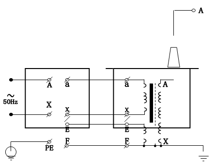
Figure 1: schematic diagram of single ZC-501A series oil immersed test transformer
2. The working principle diagram of a single oil immersed AC / DC test transformer is shown in Fig. 2. In the figure, the high-voltage bushing is equipped with a high-voltage silicon stack, which is connected in series in the high-voltage circuit for half wave rectification to obtain high DC voltage. When a short-circuit rod is used to short-circuit the high-voltage silicon stack can be obtained as AC output state, and as DC output state when the short-circuit pole is cancelled.
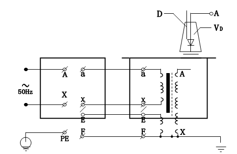
Figure 2: schematic diagram of single AC / DC test transformer
In the picture: D - short circuit rod VD - high voltage silicon stack
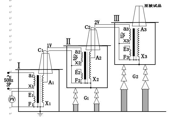
Figure 3: cascade wiring schematic diagram of three test transformers
In the figure: p-capacity (kVA) v-voltage (kV) G1, G2 - insulation support
The principle of high voltage silicon stack in high voltage bushing of test transformer is the same as the above figure.
3. The wiring principle of three test transformers in series to obtain higher voltage is shown in Fig. 5. The cascade high-voltage test transformer has great advantages because the whole test device is composed of several single test transformers. The single test transformer has small capacity, low voltage and light weight, which is convenient for transportation and installation. Since it can be connected in series with the output voltage of a single test transformer several times higher, it can also be separated into several sets of single test transformer for separate use. The investment of the whole set of equipment is small and economical. In Figure 3, there is one excitation winding A1, C1 and A2, C2 in each unit test transformer of the first and second stages. In the basic principle of three series test transformers, the low-voltage power supply is added to the primary winding a1x1 of test transformer I, and the output voltage of single test transformer I, II and III is V. The excitation windings A1 and C1 supply power to the primary winding of the second stage test transformer II, and the excitation windings A2 and C2 of the second stage test transformer II supply power to the primary winding of the third stage test transformer III. The box of the second level test transformer II and the third level test transformer III are respectively at the high potential of 1V and 2V to the ground, so the box body is insulated to the ground, and the box of test transformer I is grounded. In this way, the rated output voltage to ground of the first, second and third test transformers are 1V, 2V and 3V respectively, and their rated capacities are 3P, 2P and 1P respectively.
4. The wiring diagram of ZC-501A series oil immersed test transformer for power frequency withstand voltage test is shown in Figure 4.
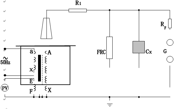
Figure 4: wiring diagram of power frequency withstand voltage test
In the figure:
R1 - current limiting resistance FRC - resistance capacitance voltage divider RF - ball gap protection resistance G-ball gap CX - test object
Note: the high voltage tail must be grounded reliably
In the power frequency withstand voltage test, the current limiting resistance R1 should be selected according to the rated capacity of the test transformer. If the rated output current of high-voltage side is 100-300ma, 0.5-1 Ω / V (test voltage) can be taken; when the rated output current of high-voltage side is above 1A, 1 Ω / V (test voltage) can be taken. Water resistance is commonly used as current limiting resistance. The length of the pipe can be considered as 150kV / m. the thickness of the pipe should have sufficient heat capacity (preparation method of water resistance liquid: use distilled water to add appropriate amount of copper sulfate to make various resistance values).
Ball gap and protection resistance: when the voltage exceeds the setting value of ball gap (generally 110% ~ 120% of the test voltage), the ball gap discharge will protect the tested object. The ball gap protection resistance can be selected as 1 Ω / V (test voltage).
In the power frequency withstand voltage test, the voltage measured at the low voltage side (instrument voltage) is not very accurate. The reason is that there is leakage reactance in the test transformer, and there must be voltage drop or capacitance rise on this leakage reactance, so that the voltage on the test object is lower or higher than the voltage reflected in the low-voltage side measuring voltmeter. In the power frequency withstand voltage test, the voltage on the test object is higher than the output voltage of the test transformer, which is the so-called capacitance rise phenomenon. In the induction withstand voltage test, the leakage reactance of the test transformer must have voltage drop. In order to accurately measure the voltage applied on the test object, FRC resistance capacitance voltage divider is often connected to the high voltage side to measure the voltage (see Figure 5).
Operation precautions of power frequency voltage withstand test
1) The test personnel should do a good job in the division of labor and clarify the method of mutual contact. There is also a special person to monitor the site safety and observe the state of the sample.
2) The test object should be cleaned and absolutely dry to avoid damage to the test object and the error caused by the test.
3) For large-scale test, air lift test should be carried out first. In other words, when the test object is not connected, boost the voltage to the test voltage, calibrate various meters and adjust the ball gap.
4) The rate of pressure rise should not be too fast, and sudden pressurization must be prevented. For example, when the voltage regulator is not in zero position, it is suddenly closed. The power supply can not be cut off suddenly. Generally, the switch should be opened when the voltage regulator drops to zero.
5) When the voltage rises to the test voltage, start timing. After 1min, the power supply can be turned on only when the voltage drops rapidly below 1 / 3 of the test voltage.
6) During the step-up or voltage withstand test, if the following abnormal conditions are found, the voltage shall be reduced immediately and the power supply shall be cut off. Stop the test and find out the reasons: ① the pointer of the voltmeter swings greatly; ② the insulation is burnt or smoking; ③ there is abnormal sound in the tested object.
7) Before and after the withstand voltage test, the insulation resistance shall be measured and the insulation condition shall be checked.
5. The wiring schematic diagram of test transformer during DC withstand voltage or leakage test of test object is shown in Fig. 7.
Note: in this test, the short circuit rod "d" should be pulled out first, as shown in Fig. 5.
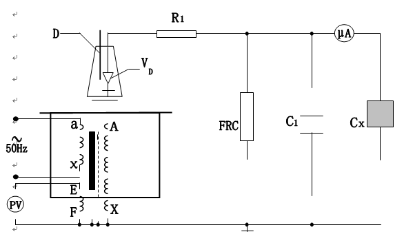
Figure 5: HV DC leakage test wiring diagram


