Dielectric loss tester is a high-precision instrument for measuring dielectric loss tangent and capacitance of various high-voltage power equipments in power plants and substations. Due to the use of frequency conversion technology, it can ensure accurate measurement under strong electric field interference. The instrument is operated by English menu, and the whole process is measured automatically by microcomputer.
The instrument is also suitable for measuring tgδ and capacitance of high-voltage electrical equipment in workshops, laboratories and scientific research institutions. It is more convenient, simple and accurate to test the loss of insulating oil.
The instrument can be used to measure the ungrounded or directly grounded high-voltage electrical equipment by positive and negative wiring method, and can also measure the tgδ of the capacitor voltage transformer and the capacitance of the main capacitance C1 and C2.
The instrument is equipped with high voltage step-up transformer, and safety protection measures such as zero crossing closing and lightning protection are adopted. During the test, the output voltage of 0.5kV-10kV is of different grades, and the operation is simple and safe.
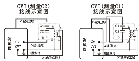
Schematic wiring diagram:
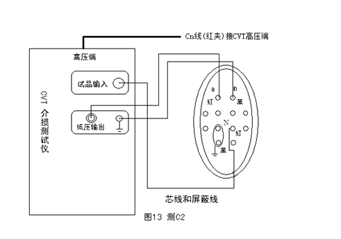
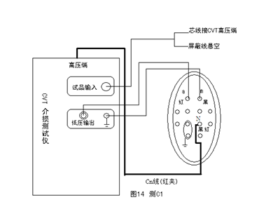
Actual wiring diagram
(1) C2 measurement: see Fig. 13 for wiring
A: The terminal in the junction box is opened to the ground, and all secondary wiring is suspended. Pay attention to make a record and restore it after the test.
B: Turn on the main power supply and internal high voltage permissive switch of dielectric loss meter.
C: Move the cursor to "connection mode" and press "ENT". Press

or

to select CV, Press the "ESC" key.
D: Move the cursor to "measured voltage" and select 1kV, press "ESC"; move the cursor to "start measurement", press "ENT" key to start measurement and wait for the result to be displayed. After the display results are displayed, if you want to print the results, press the "ENT" key.
(2) Test C1: the wiring is shown in Figure 14, and the basic operation is the same as C2 measurement.
(3) Note: only test C1 and C2 in CVT test mode; CVT will be damaged in forward or reverse connection mode!!!
Note: point N is the tail end of capacitor C2, and it needs to be disconnected from other connecting parts during measurement.
Attention should be paid to the fact that the Cn wire (red clip) should be suspended and cannot contact the ground, otherwise the additional dielectric loss to the ground will cause error. A thin cable can be used to connect the high-voltage socket with the CVT sample and hang it. In addition, considering the series partial voltage effect between C2 or C1 and internal Cn, its capacitance can be calibrated according to the following formula:
Among them, Cc is the empirical value of calibration, including the influence of Cn and the capacitance of high voltage line to ground, and its value can be taken as 110pf.
Wiring of small capacitance sample
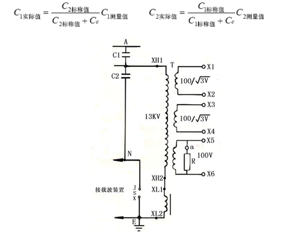 Fig15 Schematic diagram of CVT
For small capacitors, when the air humidity is high, the tgδ is affected by its surface state, and the dielectric loss measurement value is abnormal and unstable. At this time, the shielding ring can be used to absorb the leakage current on the surface of the test object, and its shielding electrode is grounded in the positive connection method, and the shielding layer of Cx is connected when the reverse connection method is adopted; this method may change the electric field distribution inside the tested equipment and affect tgδ; this connection method is adopted for both standard capacitors and standard dielectric loss capacitors.
6. Refer to section 9 "reference wiring method" for wiring method of some equipment


