The correct use of a digital partial discharge tester involves four core steps: preparation before operation, standardized testing process, data recording and analysis, and safety precautions. These steps should be adjusted according to the type of equipment (such as ultra-high frequency, ultrasonic, pulse current method). The following is a detailed operation guide:
1. Preparation before operation: Ensure that the equipment is compatible with the environment
① Equipment inspection and calibration
a. Appearance inspection: Confirm that the tester housing is not damaged, the sensors (such as ultra-high frequency antennas, ultrasonic probes) are securely connected, and the cables are not exposed or broken.
b. Function self-check: After power-on, check whether the display screen, buttons, and indicator lights are normal, and run the self-check program (such as detecting the background noise level for ultra-high frequency equipment).
c. Calibration operation:
Pulse current method: Use a standard pulse generator to inject a known charge (such as 50pC), and verify that the error between the displayed value of the device and the standard value is ≤±5%.
Ultrasonic method: In a non-discharge environment, adjust the sensitivity to ensure background noise is ≤20dB to avoid false alarms.
UHF method: Test in a shielded room to confirm that the equipment can detect simulated discharge signals (such as metal tip discharge).
② Confirmation of environmental conditions
a. Temperature and humidity: Ensure that the ambient temperature is within the range of -10℃ to 45℃, and the relative humidity is ≤95% (without condensation), to avoid high humidity causing sensor short circuits or signal attenuation.
b. Electromagnetic interference: Keep away from strong interference sources such as frequency converters and radio towers. Use a shielding box or filter when necessary. For example, when testing inside a substation, turn off nearby mobile phones or walkie-talkies.
c. Safety Distance: When testing high-voltage equipment (such as transformers and GIS), maintain a safety distance of ≥0.7 meters from the live part (in accordance with the DL/T 417-2006 standard).
③ Status check of the tested equipment
a. Visual inspection: Confirm that the equipment has no obvious defects such as oil leakage, abnormal odor, or abnormal vibration.
b. Operating parameters: Record the operating data of the tested equipment, such as voltage, current, and temperature, as a reference for analyzing partial discharge. For example, when the transformer load rate exceeds 80%, partial discharge may intensify.
c. Historical data: Retrieve previous test reports of the equipment and compare the trend of changes with the current test results.
2. Test process specification: step-by-step operation and parameter setting
① Sensor installation and connection
a. Ultra-high frequency method: Place the UHF sensor closely against the non-metallic part of the GIS basin insulator or cable terminal, using a couplant to reduce contact resistance. For example, when testing 110kV GIS, the sensor needs to cover all gas compartment intervals.
b. Ultrasonic method: Align the ultrasonic probe with the potential discharge area of the equipment (such as switchgear contacts, transformer bushings), keep it perpendicular to the surface, and maintain a distance of ≤5cm.
c. Pulse current method: Clip the high-frequency current transducer (HFCT) onto the equipment grounding wire, ensuring that the direction is consistent with the current flow direction to avoid magnetic field interference.
② Parameter setting
a. Detection frequency band:
UHF method: Set the frequency band to 300-1500 MHz to avoid low-frequency interference (such as 50 Hz power frequency).
Ultrasonic method: Select a frequency band of 20-60kHz to filter mechanical noise (such as fan and transformer vibration).
b. Trigger threshold: Set the alarm threshold according to the equipment type, for example: transformer: ≤100pC (IEC 60076 standard). Cable: ≤10pC (GB/T 3048.12 standard). GIS: ≤5pC (DL/T 603-2017 standard).
c. Sampling time: Set the number of sampling points per power frequency cycle (e.g., 100 points/cycle) to ensure that the details of the discharge pulse can be captured.
③ Test execution
a. Static test: Apply rated voltage or gradually increase the voltage to the test voltage (such as 1.1Un) to the stationary equipment (such as transformers, cables), continuously monitor for more than 10 minutes, and record the discharge amplitude, phase, and frequency.
b. Dynamic testing: Conduct online monitoring of equipment in operation (such as switchgear), continuously record data for 24 hours, and analyze the relationship between discharge, load, and temperature.
c. Positioning test: UHF method: Calculate the location of the discharge point by measuring the time difference of signals received by multiple sensors (accuracy up to 0.5 meters). Ultrasonic method: Move the probe to find the maximum signal point and estimate the distance based on the speed of sound (approximately 340m/s). Pulse current method: Locate the cable fault point through traveling wave method or time difference method.
3. Data recording and analysis: from raw data to fault diagnosis
Data recording
a. Real-time display: Observe the PRPD (Phase-Resolved Pulse Distribution) spectrum on the display screen of the tester and record the phase concentration area of the discharge pulse (such as 0°~90° or 180°~270°).
b. Data storage: Save test data to device memory or export it to a computer in formats such as CSV, Excel, or specialized software formats (e.g., PQP files).
c. Report generation: Fill in information such as the testing date, equipment name, environmental conditions, test parameters, etc., and attach the PRPD spectrum and discharge trend diagram.
② Data analysis
a. Discharge type identification:
Corona discharge: The phase is concentrated near the voltage peak, with a low amplitude (<100pC).
Suspended discharge: The phase distribution exhibits a bimodal pattern, with amplitudes exceeding 500pC.
Surface discharge: The phase distribution is relatively wide, and the amplitude fluctuates over time.
b. Trend analysis: Compare historical data. If the discharge volume increases exponentially (e.g., by 20% per week), immediate action is required.
c. Correlation analysis: Combine data from oil chromatography analysis (such as excessive acetylene content in transformers) and infrared thermography (such as localized overheating) to comprehensively determine the type of fault.
4. Safety precautions: Prevent personal and equipment risks
① Personal safety
a. High-voltage protection: When testing high-voltage equipment, wear insulating gloves, insulating shoes, and use an insulating operating rod.
b. Arc protection: Avoid dismantling sensors or cables when the equipment is live. If necessary, apply for a power outage to carry out the operation.
c. Radiation protection: During testing using the ultra-high frequency method, keep away from the radiation direction of the sensor and avoid prolonged exposure to high-frequency electromagnetic fields.
② Equipment safety
a. Overvoltage protection: During pulse current testing, ensure that the test voltage does not exceed 1.2 times the rated voltage of the equipment.
b. Short circuit prevention: Before contacting the equipment with the ultrasonic probe, ensure that the surface is free of metal debris or conductive liquids.
c. Anti-static: When operating in a dry environment, use an anti-static wrist strap to prevent static electricity from damaging the equipment circuit.
③ Emergency response
a. Equipment malfunction: If the tester displays abnormalities (such as no signal, garbled text), immediately stop the test and check the power supply and sensor connections.
b. Abnormality of the tested equipment: If the equipment experiences an accident such as explosion or smoking during testing, immediately evacuate the scene and report the incident, rather than attempting to handle it yourself.
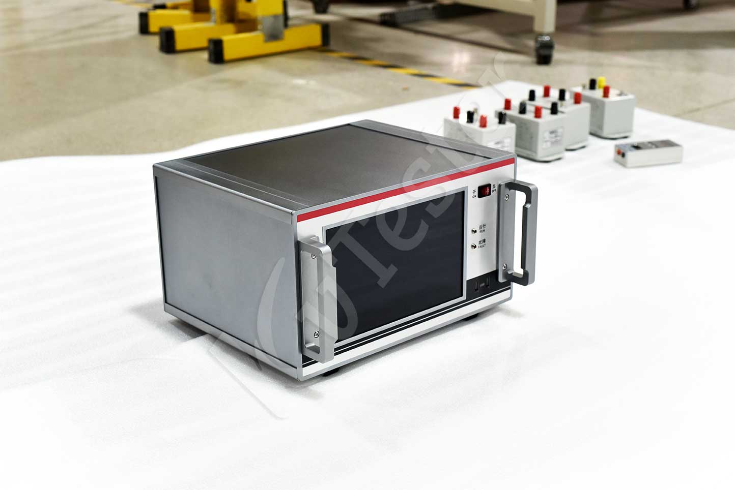
ZC-254-IV digital partial discharge detector adopts an integrated machine design, which is easy to operate. This instrument is suitable for type testing, factory testing, and handover testing of high-voltage products, and can complete quantitative testing of partial discharge of motors, transformers, cables, bushings, capacitors, transformers, lightning arresters, switches, and other high-voltage electrical appliances.
Kvtester Electronics Technology Co.,Ltd. is a high-tech enterprise specializing in power testing, testing, research and development, production, and sales of testing equipment. It has been engaged in the electrical testing industry for many years, and its products are of high quality. We welcome customers to come and purchase. Service hotline: 0086-27-81778799, to learn more, visit the official website: www.kvtester.com


