The lightning impulse test device is a key equipment for simulating lightning overvoltage to test the insulation strength of power equipment. Its core principle is to generate lightning impulse waveforms that meet standard requirements through fast charging, high-voltage triggering, and waveform control technology (such as 1.2/50 μ s full wave or 1.2/2-5 μ s truncated wave). The following is a detailed step-by-step analysis of its working principle:
1. Energy storage stage: High voltage capacitor charging
① Low voltage power input
The device is powered by a low-voltage AC power source (such as 380V/50Hz), which is converted into DC power through a rectifier circuit to provide energy for the high-voltage charging circuit.
② High voltage charging circuit
a. Charging transformer: steps up low-voltage direct current to several thousand volts to several million volts (depending on the test voltage requirements).
b. Current limiting resistor: limits the charging current, prevents capacitor overload, and controls the charging speed (usually adjustable voltage rise rate per second).
c. High voltage capacitor group: As an energy storage component, the capacitance value ranges from a few nanofarads (nF) to several hundred microfarads (μ F), selected according to the experimental energy requirements (E=0.5 × C × U ²). For example, testing a 100kV, 1nF device requires storing 5J of energy.
③ Charging control
Real time monitoring of capacitor voltage through voltage sensors, automatically cutting off the charging circuit when the voltage reaches the preset value. Some devices support staged charging to achieve more precise voltage control.
2. Waveform generation stage: rapid discharge and waveform control
① Trigger system startup
A. Trigger method:
a. Ball gap triggering: By using a high-voltage pulse to penetrate the air gap (ball gap), the energy of the capacitor is instantly released.
b. Three electrode gap triggering: Adding auxiliary electrodes on top of the ball gap to improve triggering stability.
c. Laser triggering: Using laser to break down gas and generate plasma channels, achieving nanosecond level triggering accuracy (suitable for high-precision experiments).
B. Trigger synchronization: The trigger signal is synchronized with the charging voltage to ensure waveform repeatability (error<± 1%).
② Waveform forming circuit
A. Full wave generation:
a. The capacitor discharges to the device under test through the ball gap, forming a 1.2/50 μ s waveform.
b. The wavefront time (1.2 μ s) is determined by the capacitance and loop inductance (L) (T1 ≈ π√ (LC)/2).
c. The half peak time (50 μ s) is determined by the circuit resistance (R) and capacitance (C) (T2 ≈ 0.7RC).
B. Cut wave generation:
a. Connect cutoff devices (such as cutoff ball gaps or cutoff rods) in series in the full wave circuit.
b. When the voltage reaches the preset cutoff value, the cutoff device operates and the waveform is truncated to 1.2/2~5 μ s.
C. Waveform adjustment technology
a. Inductance adjustment: Adjust the wavefront time through a variable inductor (increase inductance to extend wavefront, decrease inductance to shorten wavefront).
b. Resistance adjustment: Adjust the half peak time through a variable resistor (increase resistance to extend half peak, decrease resistance to shorten half peak).
c. Capacitor parallel/series connection: By adjusting the total capacitance value through capacitor combination, it affects the waveform energy and duration.
3. Measurement and recording stage: waveform acquisition and analysis
① High voltage divider
a. Resistance voltage divider: suitable for low voltage testing (<100kV), measuring high voltage through series resistance voltage division.
b. Capacitive voltage divider: suitable for high voltage testing (>100kV), measuring high voltage through series capacitive voltage division, with high-frequency response characteristics.
c. Voltage divider calibration: It is necessary to regularly calibrate the voltage divider to ensure measurement accuracy (error<± 1%).
② Oscilloscope and Data Acquisition
a. Bandwidth requirement: Choose an oscilloscope with a bandwidth of ≥ 100MHz to capture waveform details (such as the fast rising edge in the cutoff test).
b. Sampling rate: The sampling rate should be ≥ 1GS/s and the resolution should be ≥ 12bit to avoid data distortion.
c. Trigger synchronization: The oscilloscope trigger signal is synchronized with the test device trigger signal to ensure complete waveform recording.
③ Waveform analysis software
a. Parameter calculation: Automatically calculate key parameters such as wavefront time (T1), half peak time (T2), and peak voltage (Upeak).
b. Compliance assessment: Compare the measured waveform with the standard waveform (such as IEC 60060-1) to determine whether the test is qualified.
c. Report generation: Automatically generate test reports, including waveform diagrams, parameter tables, and conclusions.
4. Security and protection mechanisms
① Overvoltage protection
a. Hardware protection: Connect an overvoltage protection relay in series in the charging circuit, and automatically cut off the power supply when the voltage exceeds the preset value.
b. Software protection: By monitoring the voltage through the control system, the emergency stop function is triggered when the voltage is abnormal.
② Grounding and shielding
a. Grounding system: The device casing, tested equipment, and measurement system must be reliably grounded (grounding resistance<0.5 Ω) to prevent potential floating.
b. Shielding design: The high-voltage circuit uses shielded cables to reduce the impact of electromagnetic interference (EMI) on measurement results.
③ Safety interlock
a. Door lock interlock: When the test door is not closed, the device cannot start charging or trigger.
b. Personnel protection: Set up safety fences in the experimental area, equipped with infrared sensing or laser aiming devices to prevent personnel from entering by mistake.
5. Typical application scenario examples
① Transformer lightning impulse test
a. Test voltage: Select the test voltage based on the rated voltage of the transformer (for example, a 220kV transformer requires a 500kV full wave test).
b. Waveform requirement: 1.2/50 μ s full wave+1.2/2 μ s cutoff, to verify the transformer insulation's withstand capability under lightning overvoltage.
c. Measurement focus: Pay attention to whether there is oscillation or overshoot in the waveform (overshoot<5% Upeak).
② Residual voltage test of lightning arrester
a. Test voltage: Apply standard lightning impulse voltage (such as 8/20 μ s waveform) and measure the residual voltage of the lightning arrester.
b. Waveform requirements: wavefront time of 8 μ s, half peak time of 20 μ s, simulate lightning current waveform.
c. Measurement focus: The residual voltage value should be lower than the rated voltage of the lightning arrester (such as 10kV lightning arrester residual voltage<17kV).
③ Cable insulation test
a. Test voltage: Select the test voltage based on the rated voltage of the cable (e.g. 30kV test voltage is required for 10kV cables).
b. Waveform requirement: 1.2/50 μ s full wave, verify the breakdown characteristics of the cable insulation layer under lightning overvoltage.
c. Measurement focus: Pay attention to whether the cable has undergone partial discharge or breakdown.
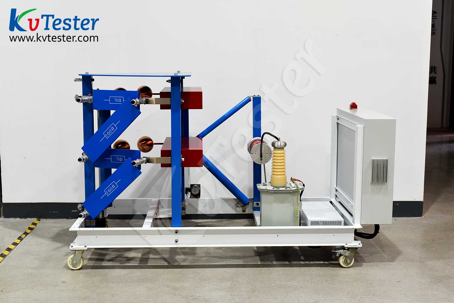
The ZCCJ-800kV/80kJ impulse voltage generator adopts a four column H structure, with a steel bracket consisting of a single flange and a parallel external single capacitor, forming a stable structure consisting of one stage. The main equipment is of 8 levels, forming a combined tower structure, with each level stacked step by step for easy disassembly and maintenance, and the overall structure is stable.
This set of equipment is mainly designed to meet the lightning full wave and steep wave waveform tests of electrical equipment such as power insulators.The basic configuration of the equipment includes a charging device, an impulse voltage generator body, a weak damping capacitor voltage divider, a steep wave device, a fast resistor voltage divider, and other control and measurement devices.
Kvtester Electronics Technology Co.,Ltd. is a high-tech enterprise specializing in power testing, testing, research and development, production, and sales of testing equipment. It has been engaged in the electrical testing industry for many years, and its products are of high quality. We welcome customers to come and purchase. Service hotline: 0086-27-81778799, to learn more, visit the official website: www.kvtester.com


