The partial discharge detection system has a unique dual channel simultaneous measurement function, which can conveniently measure multiple samples simultaneously or multiple points of a single sample simultaneously. This makes it possible to diagnose the discharge location of large transformers, and this method has been successfully applied to the detection of large transformers and online monitoring of transformer partial discharge in substations.
Principle of partial discharge detection system:
When the test sample generates a partial discharge, there is an instantaneous voltage change at both ends of the test sample Cx Δ U. After coupling a coupling capacitor Ck to the detection impedance Zm, a pulse current I is generated in the circuit. By sampling, amplifying, and displaying the pulse voltage generated by the detection impedance Zm, the apparent discharge amount and other parameters of partial discharge can be measured. The pulse current method mainly utilizes the lower frequency part of the partial discharge signal spectrum to avoid radio interference.
The partial discharge detection system is equipped with RLC type detection impedance to measure the pulse signal generated by partial discharge and suppress the power frequency and other low-frequency interference signals of the experimental power supply.
The partial discharge detection system is a testing system in the form of pulse peak indication, with functions such as computer programmable filtering, amplification, sampling, storage, and display. The data collection is synchronized with the test voltage. Can use direct method, bridge balance method, complex rate n, average discharge current I, square rate D, and can create various graphs: q-n, q- ф、 Q- ф- The partial discharge testing system can detect ultrasonic signals with partial discharge levels less than 1000pC.
Partial discharge refers to the phenomenon of discharge or breakdown within a local range of insulation medium caused by uneven distribution of electric field and high local field strength of an insulator. It is the main cause of insulation degradation and an important symptom and manifestation of degradation, closely related to the degradation and breakdown of insulation materials. Therefore, the effective detection of partial discharge in power equipment is of great significance. Currently, the principle of ultrasonic partial discharge detection is widely used in domestic and foreign power systems to achieve insulation detection of electrical equipment.
Causes of partial discharge:
For any insulation structure, the presence of bubbles, oil gaps, and insulation weaknesses inside is inevitable. These bubbles, oil gaps, and insulation weaknesses are usually formed during the equipment manufacturing process. For example, for oil-immersed transformers, due to incomplete paint, drying, and vacuum treatment during the manufacturing process, some cavities will inevitably be formed in the electric cylinder, insulating cardboard, and interlayer of the insulating paper used in the product, and there will be some bubbles in the cavities. Due to the lower dielectric coefficient of gas compared to insulating materials such as oil and paper, the electric field strength borne by the air gap is higher than that on oil-paper insulation (E=KQ/ ε R where K is a constant; ε Is the dielectric coefficient of the medium; R is the distance from the charge to the point, and when the applied voltage reaches a certain value, partial discharge will first occur in these air gaps. In addition, the oil film inside the oil paper insulation, the oil gap in the oil partition insulation structure, especially the "wedge type" oil gap, sharp corners and burrs in metal components, wires, and other parts, as well as local areas with concentrated electric fields and high field strength, are also prone to partial discharge.
1. The causes and general parts of air gaps
① Due to impure purification, poor treatment, or insufficient static electricity time of transformer oil, a small amount of bubbles (air gaps) are present in the oil.
② Due to the imperfect manufacturing process of insulation components and products, there are some air gaps in laminated wooden boards, laminated cardboard, corner rings, electrostatic board bends, wire smashes, and insulation overlap gaps.
③ Due to insufficient vacuum degree and vacuum time during vacuum treatment and vacuum injection of oil immersed transformers, some air gaps remain in the oil and oil paper insulation.
④ Due to insufficient vacuum degree and vacuum time during vacuum injection of resin insulated dry-type transformers, some bubbles remain in the resin insulation.
⑤ Due to the difference in thermal expansion coefficient between the composite insulation formed by resin and glass fiber curing in resin insulation (wrapped insulation) of dry-type transformers and the thermal expansion coefficient of copper and aluminum wires, there are some air gaps in stress cracking areas (between resin layers).
2. Structural reasons
Due to the unreasonable insulation structure of the transformer, the distribution of electric field inside the insulation is uneven. If the electric field intensity in certain parts is lower than the initial discharge power level of the insulating medium, these parts are prone to partial discharge.
3. Material reasons
Copper and aluminum wires, copper and aluminum foil surfaces are not smooth and have burrs, which not only cause partial discharge, but also damage the inter turn insulation, causing inter turn insulation short circuits.
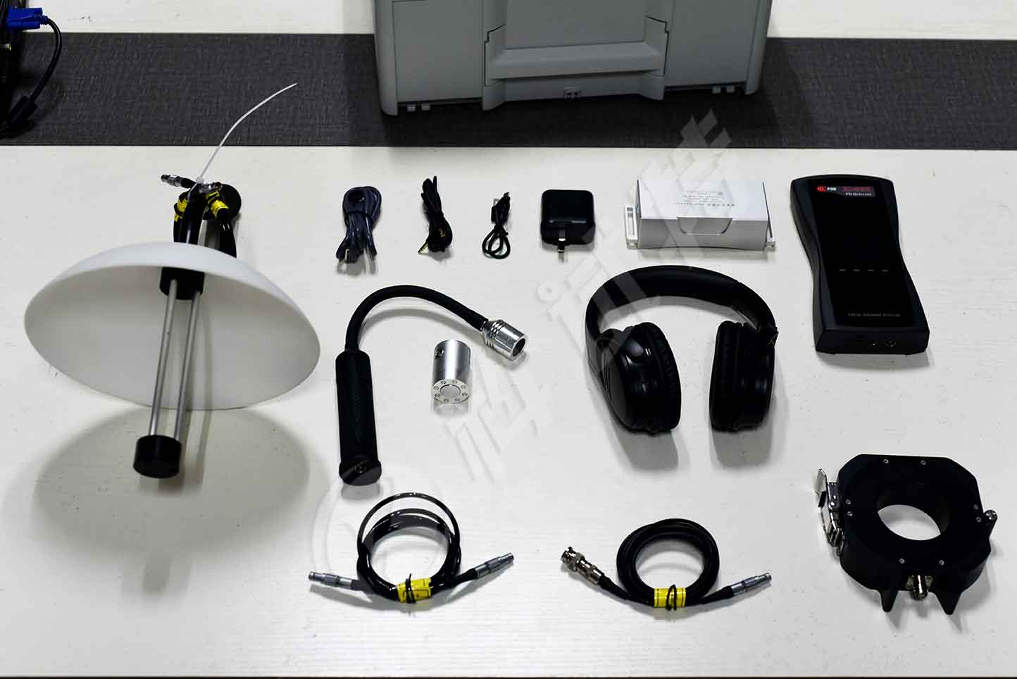
The ZC-830 partial discharge detector can be widely used for partial discharge detection in power systems, including insulation status detection of high-voltage switchgear, ring network cabinets, voltage/current transformers, transformers (including dry-type transformers), GIS, overhead lines, cables, and other equipment. The discharge degree of electrical equipment is measured by the following indicators:
1. Partial discharge intensity detection: By measuring the discharge signal within one power frequency cycle, the intensity of partial discharge is characterized by the maximum value (dB) in the discharge pulse sequence.
2. Partial discharge frequency detection: The device measures the discharge signal within one power frequency cycle, extracts discharge pulses, and characterizes the frequency of partial discharge based on the number of discharge pulses.
Kvtester Electronics Technology Co.,Ltd. is a high-tech enterprise specializing in power testing, testing, research and development, production, and sales of testing equipment. It has been engaged in the electrical testing industry for many years, and its products are of high quality. We welcome customers to come and purchase.


