At present, most circuit resistance testers on the market use a typical four wire measurement method, where a high-frequency switching power supply provides a test current greater than 100A. When the measurement button is pressed, the high-frequency switching power supply outputs a test current greater than 100A. At the same time, the sampling circuit begins to sample, and the obtained signal is amplified by an amplifier. The analog signal is converted into a digital signal by an A/D converter, and then filtered, calculated, and processed by a microprocessor Process and finally send the display to display the current and resistance values measured this time. And when there is a disconnection or poor contact in the current testing circuit, the instrument will determine the poor contact or open circuit of the current circuit based on the voltage on the current divider.

During on-site testing, circuit resistance testers designed according to conventional design principles have found a common problem: when there is poor contact or open circuit in the voltage wiring circuit of the tester, the tester will also display a numerical value, and the following situations will occur:
① The voltage circuit is open and there is no strong electric field interference at the testing site. In this case, due to the differential mode voltage input by the amplifier being basically 0, the test value displayed by the instrument is close to 0. If the tester has sufficient on-site testing experience, it can be determined that the voltage circuit test line of the instrument is abnormal. After excluding the abnormal voltage circuit test line of the instrument, the final correct test result can be obtained; Otherwise, it may be mistaken for a problem with the tester and interrupt the test. Replacing or refurbishing the instrument will delay the power outage time and bring unnecessary trouble to the testing work.
② Poor contact in the voltage circuit. In most cases, the wiring terminals of the circuit breaker will produce oxide film or oil film on the outer surface of the terminal block after long-term operation. When the voltage test clamp of the circuit resistance meter is connected to such a terminal block, poor contact may occur. Both the voltage test wire clamp itself must generate a certain contact resistance, which reaches a value equivalent to the internal resistance of the voltage sampling circuit, It will have a serious impact on the test results.
③ If the voltage circuit is open or has poor contact (the visible contact resistance R1 is infinite when the circuit is open), there is strong electromagnetic interference at the testing site. For example, if the busbar is live, the live busbar will pass through a capacitor with air as the medium, interfering with the two voltage test lines of the tester. Due to the interference, differential mode voltage will appear at both ends of the voltage collection line of the circuit tester.
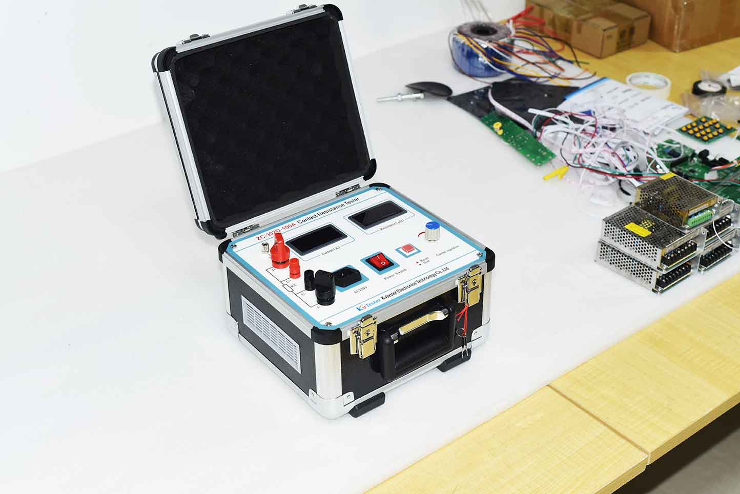
ZC-302D-100A Contact Resistance Tester meets the criteria of the latest power system standard--DL/T845.4-2004. The tester bases on the combination of High-frequency switching power supply technology and digital circuit technology. It is suitable for measurement of loop resistance of Switching Control Equipment. Test current of the Tester is DC-100mA which is recommended in the national standards. The Tester can measure the loop resistance and display in the monitor. Its accuracy and stability meet most power systems’ requirements in maintenance and loop resistance of high-voltage switches.
Kvtester Electronics Technology Co.,Ltd. is a high-tech enterprise specializing in power testing, testing, research and development, production, and sales of testing equipment. It has been engaged in the electrical testing industry for many years, and its products are of high quality. We welcome customers to come and purchase.


