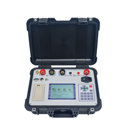
Generator rotor AC impedance tester is the latest enhanced generator rotor AC impedance tester launched by our company. The instrument adopts the most advanced high-speed microprocessor technology, which has more powerful function, better performance and more convenient use. It has the characteristics of high reliability, easy operation, high precision, small and light. At present, it is at the leading level in China.
-
Switch on the working power of the instrument, turn on the power switch, and after the instrument is reset, enter the interface diagram as shown in Fig. 1, press "↑" and "↓" keys to select "manual test", and then press "OK" to enter the "manual test parameter setting" interface as shown in Figure 1.
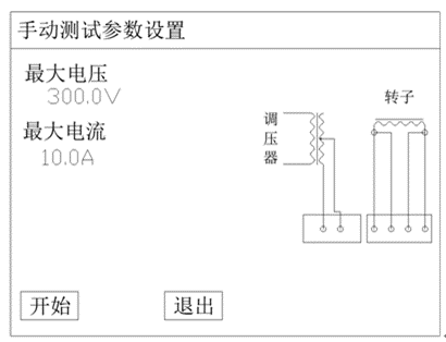
Figure 1 manual test parameter setting interface
Among them:
Equipment number: it is used to distinguish different equipment, different test properties and times. It’s good for the search in historical data and technical management.
The maximum voltage refers to the maximum voltage value to be tested in the test, with the range of 0-600V. 1.1 times of the set value is the default overvoltage protection action value of the instrument.
The maximum current refers to the maximum current value to be tested in the test, with the range of 0-120a. 1.1 times of the set value is the default over-current protection action value of the instrument.
2) Connect the voltage regulator, the instrument and the measured rotor winding according to the wiring diagram in the interface.
3) Set the above parameters according to the test needs, move the cursor and select "start test" to enter the "manual test" interface as shown in Figure 2.
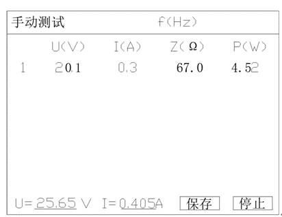
Figure 2 manual test interface
In this interface, adjust the voltage regulator to boost, when the real-time value appears the required voltage (or current) test point, press the "save" key, and the instrument will automatically collect and display a group of measurement data of each parameter under this test point; and so on Until all the required test points are tested, and then return the voltage regulator to zero.
4) After the test, the instrument interface will switch to "manual test results" interface as shown in Figure 3.
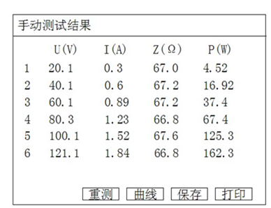
Figure 3 manual test result interface
In the current interface, you can traverse the measurement results by pressing the "↑" and "↓" keys on the keyboard. Presses “save" to save the current test results to the memory of the instrument for future reference. Press "print" to print the current test results through the panel printer. After pressing the "curve" key, the instrument will draw the "voltage current relationship" curve as shown in Figure 1 according to the measured data Line diagram.
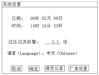
In the figure above, you can modify the date and time of the system;
The value of "over-voltage and over-current alarm" sets the multiple value of over-voltage and over-current alarm during the test, which is relative to the maximum test voltage and current set in the test.


