The transformer capacity and no load tester is a new type of instrument specially designed for the problem of bad power users escaping basic electricity charges and increasing capacity without permission. It is a high-precision instrument for measuring transformer capacity, no-load, load and other characteristic parameters. This instrument is a multi-functional measuring instrument, equivalent to the usual two kinds of testing instruments: transformer capacity tester + transformer characteristic parameter tester. It can precisely measure a series of power frequency parameters such as capacity, type, and no-load current, no-load loss; short-circuit (load) loss, impedance voltage and so on.
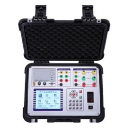
According to the type of transformer, refer to the corresponding wiring diagram for correct wiring, and then turn on the working power supply of the instrument.
Select load test in the main interface to display the load test setting interface as shown in the following figure:
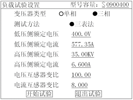
Figure 1 load test setup page
This page saves the setting value of the last test. Check and modify the setting value in this page to make it consistent with the current test transformer. In particular, pay attention to the capacity value, rated current at high voltage side and transformation ratio of current transformer represented by the last five digits of the number, so as to avoid setting value error or test current exceeding the range.
Note: in some versions of our instruments, in order to simplify the external wiring, double meter method or three meter method has been connected inside the instrument. At this time, the test method of the interface is not optional, and the wiring of the instrument can only be connected according to the wiring method of double meter or three meter method.
Select "start test" in the above figure to enter the test data interface of load test
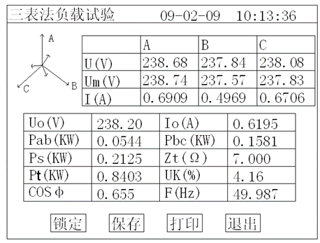
Figure 2 load test data page
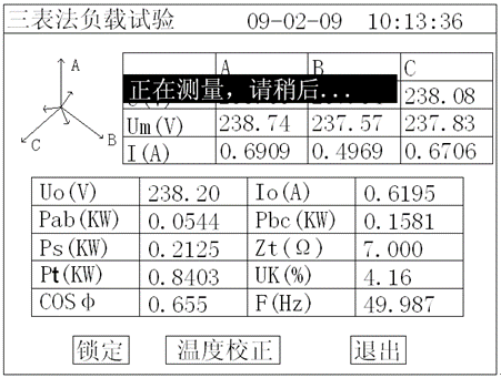
Figure 3 load loss measurement calculation page
The above figure shows all test data under current temperature during load test: Uav (V) is the average value of current three-phase voltage, Io (A) is the average value of three-phase current, Ps (KW) is the measured power under current voltage, Pt (KW) is the overload loss corrected to the rated current at the current temperature, ZT (Ω) is the short-circuit impedance at the current temperature, and Uk% is the short-circuit voltage percentage at the current temperature.
The upper left side is the vector diagram of test voltage and current. If the wiring is wrong, the page will prompt "wiring error please shut down and check"; slowly increase the test voltage through the voltage regulator, and stop boosting when Io (A) is equal to the test current of load test. Move the cursor to the "lock" button, and press the OK key for a long time. At this time, keep the voltage regulator still. When the prompt message of measuring in Figure 3 disappears, the current test result has been locked, and then the "lock" button becomes the "retest" button. At this time, please quickly operate the voltage regulator to depressurize to zero.
Note: in the process of boosting voltage, attention should be paid to UAV and IO at all times. In addition to avoiding over-voltage, it is also necessary to prevent excessive test current from damaging the instrument or the tested object when the test object is abnormal.
Select "temperature correction" in Figure 3 to display the temperature correction interface:
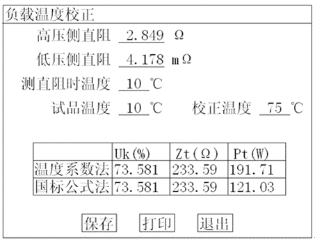
Figure 4 load result temperature correction page
The parameter setting value of this page is the setting value of the last test. Check and modify it to make it consistent with the current test object. The instrument provides two temperature correction algorithms: temperature coefficient method and national standard formula method. See the appendix below for the formula of these two algorithms.
The "save" on the page saves the current results to the random memory; the "print" button prints the current test results through the printer.


