Grounding resistance is an important parameter used to measure whether the grounding status is good. It is the resistance encountered by the current flowing from the grounding device into the ground and then passing through the ground to another grounding body or spreading to a distance. It includes the resistance between the grounding wire and the grounding body itself, the contact resistance between the grounding body and the ground, and the resistance between the two grounding bodies or the grounding body to infinity. The size of the grounding resistance directly reflects the degree of good contact between the electrical device and the "ground", as well as the scale of the grounding grid.
1、 Analysis of the reasons for inaccurate measurement:
1. Due to the fact that the grounding resistance tester tests the grounding resistance of the grounding body by emitting and receiving current through iron bars, mutual interference and errors will occur when the distance between two iron bars and between two bars and the grounding body is too close. Therefore, during measurement. The grounding body, voltage pole, and current pole are arranged in sequence, with three points in a straight line and 20 meters apart from each other.
2. When the tested grounding electrode is in the "common ground" situation, due to poor insulation or short circuit of the equipment, the grounding device generates a certain ground voltage, which makes the reading unstable during measurement. At this time, the power should be cut off for testing, or disconnected from the place where the grounding card is disconnected for testing to avoid the influence of ground voltage on the testing.
3. The depth of the iron rod inserted into the ground should be greater than 1/4 of the length of the iron rod, otherwise testing errors will occur. Therefore. During testing, the iron brazing should be drilled as deep as possible.
4. When inspecting high-rise buildings, using wires that are too long or too thick can increase line resistance and induced voltage, causing measurement errors. At this time, wires with relatively low resistance should be used to minimize measurement errors as much as possible.
5. Poor contact. When the object being tested rusts or the detection line breaks, a phenomenon of intermittent disconnection or high resistance may be found during detection. At this point, rust should be removed first. If it still cannot be ruled out, use the resistance range of a multimeter to check the conductivity of the detection line.
6. When there are materials such as soil or sand in the measured area, measurement errors may occur due to the different electrical resistivity of the upper and lower layers of soil. At this time, deep iron drills should be used to ensure full contact with the soil under the cushion layer or to avoid the cushion layer, in order to reduce measurement errors.
7. Inaccurate measurements are caused by the presence of potential differences or strong magnetic fields on the surface. At this time, it is advisable to stay as far away as possible from places with large potential differences or strong magnetic fields. If unavoidable, the detection line should be relatively shortened to reduce measurement errors.
8. When the grounding device and metal objects such as pipelines being tested are buried underground, it may change the direction of the current at each pole of the measuring instrument, causing poor or unstable measurements. At this point, it is necessary to first understand the layout of the grounding body and metal pipeline, and select a relatively less affected area for measurement.
9. Factors such as product quality issues with the instrument, failure to strictly follow the instructions, failure to repair the grounding resistance tester in a timely manner, inaccurate instrument or long-term lack of identification can also cause measurement errors.
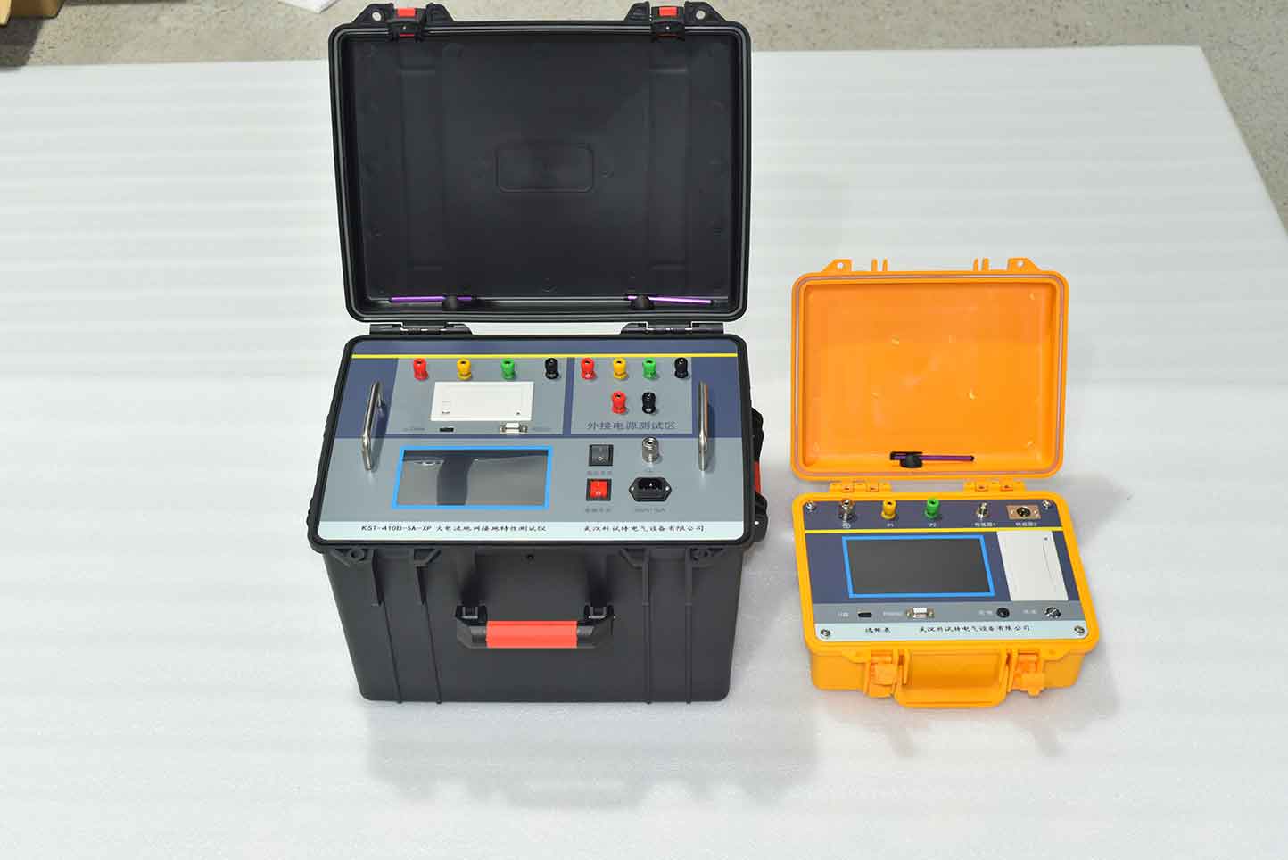
The ZC-410B-5A-XP high current grounding characteristic tester is a specialized instrument for measuring the grounding resistance of the grounding grid and the grounding conductivity between the grounding point. The instrument adopts frequency conversion anti-interference technology, which does not require high current measurement. It can accurately measure 50Hz data in a strong interference environment of the substation. The measurement results are displayed on a large LCD screen and come with a micro printer that can be printed out. The instrument can simultaneously measure the grounding impedance and grounding resistance, which can more accurately reflect the actual characteristics of the grounding grid.
Kvtester Electronics Technology Co.,Ltd. is a high-tech enterprise specializing in power testing, testing, research and development, production, and sales of testing equipment. It has been engaged in the electrical testing industry for many years, and its products are of high quality. We welcome customers to come and purchase. Service hotline: 0086-27-81778799, to learn more, visit the official website: www.kvtester.com


