The relay protection tester is a key equipment for the debugging, calibration, and maintenance of power system relay protection devices. Its usage must strictly follow the operating specifications to ensure testing accuracy and equipment safety. The following are detailed usage steps and precautions:
1. Preparation before use
① Equipment placement and grounding
Place the tester in a dry, ventilated environment without strong electric and magnetic field interference, ensuring that the equipment is placed smoothly.
Connect the power cord grounding terminal reliably to prevent static electricity induction.
② Equipment inspection
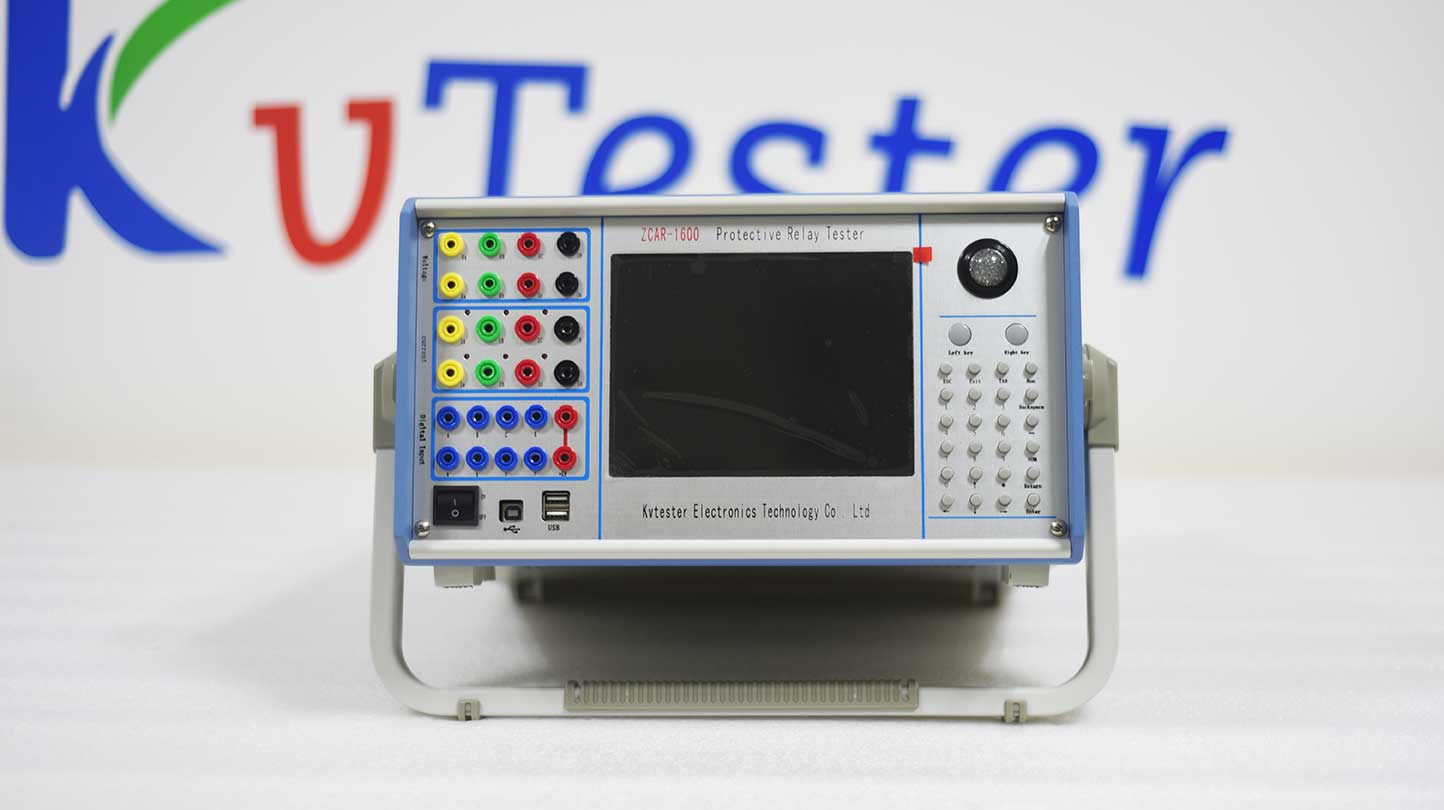
Check whether the appearance of the instrument is intact, and whether the power cord, connecting wire, etc. are not damaged.
Confirm that the instrument power switch is in the off state to avoid live wiring.
③ Connect power supply
Connect AC 220V ± 10%, 50Hz ± 5% power supply according to equipment requirements to ensure stable power supply.
2. Parameter setting and wiring
① Start equipment and calibration
Press the power switch to start the device, and after the device self checks, calibrate it to ensure accurate test results.
② Input test parameters
Voltage and current settings: Input the effective values of voltage and current according to the testing requirements, and the system automatically retains three significant decimal places.
Phase setting: Enter the phase angle within the range of -180 °~360 °, and the system will automatically switch if it exceeds the range.
Upper limit value setting: Set the maximum effective value allowed for each phase output to prevent damage to the device caused by excessive output.
③ Wiring method
Connect the current output terminal of the tester to the relay current coil and the voltage output terminal to the relay voltage coil.
Connect the normally open/normally closed contacts of the relay to the input terminal of the tester to ensure correct wiring.
3. Test operation
① Select testing program
Select the corresponding testing program according to the testing requirements, such as "AC test", "DC test", etc.
② Set test variables
Choose the appropriate current step or voltage step based on the magnitude of the relay's operating current.
When the operating current is less than 35A, one phase current can be selected as the variable; When it is greater than 35A, two-phase or three-phase parallel current output can be used.
③ Start testing
After confirming that the parameter settings are correct, start the testing program and the device will display the test results in real time, including action time, action type, action value, etc.
④ Record data
Record test data as needed for subsequent analysis and evaluation.
4. Post test processing
① End test
After the test is completed, close the testing program and disconnect the device power.
② Equipment maintenance
Regularly clean and inspect the testing equipment to ensure that it is in good condition.
5. Precautions
① Safe operation
Strictly follow the operating procedures, avoid contact with high-voltage parts during the testing process, and prevent electric shock accidents.
② Exception handling
In case of equipment failure to start or abnormal test results, the power supply of the equipment should be immediately turned off, and the wiring and parameter settings should be checked for correctness.
③ Heat dissipation requirements
When the output current exceeds 10A, it is necessary to ensure that the equipment has at least 60 seconds of heat dissipation time to avoid overheating and damage.
④ Prohibited operation
It is prohibited to introduce external AC/DC power into the voltage source, current source, and output socket of the tester to prevent damage to the equipment.
6. Special requirements for different types of testing
① Low voltage relay testing
Select a higher initial voltage value, gradually decrease the voltage in steps until the relay operates, and record the operating voltage value.
② Differential protection test
Differential current and braking current need to be set to verify the operating characteristics of differential protection.
③ Recloser test
Simulate line faults and test the action logic and timing coordination of the reclosing device.
Kvtester Electronics Technology Co.,Ltd. is a high-tech enterprise specializing in power testing, testing, research and development, production, and sales of testing equipment. It has been engaged in the electrical testing industry for many years, and its products are of high quality. We welcome customers to come and purchase. Service hotline: 0086-27-81778799, to learn more, visit the official website: www.kvtester.com


