The high-voltage switch dynamic characteristic tester uses multi physical quantity synchronous acquisition and high-speed signal processing technology to capture the mechanical motion and electrical characteristics of the switch opening and closing process in real time, generate time stroke curves, and calculate key parameters. Its working principle can be decomposed into four core links: data acquisition, signal processing, parameter calculation, and result output. The following is a specific analysis:
1. Data collection: Multi sensor collaborative sensing
The tester synchronously collects the switch motion status and electrical characteristics through four types of sensors: displacement sensor, acceleration sensor, opening and closing coil current sensor, and auxiliary contact signal
① Displacement sensor (core)
Type: Linear grating ruler (accuracy ± 0.01mm), rotary encoder (accuracy ± 0.1 °), or laser ranging module.
Function: Real time measurement of the travel of the moving contact, generating a travel time curve (for example, a 550kV circuit breaker with a total travel of 120mm needs to be opened within 10ms).
Application scenarios: Calculate the speed of just opening/closing (average speed before and after 10ms of contact separation/contact), overtravel (additional travel after complete contact of the contact).
② Acceleration sensor (auxiliary verification)
Type: Piezoelectric accelerometer (range ± 500g).
Function: Calculate the stroke through secondary integration, cross validate with displacement sensor data, and eliminate sensor installation errors (such as compensating for tilt angles greater than 5 °).
③ Opening and closing coil current sensor
Type: Hall current sensor (accuracy ± 0.5%).
Function: Monitor changes in electromagnetic force of the operating mechanism, identify faults such as iron core jamming and coil disconnection (such as a plateau period in the coil current waveform, indicating insufficient energy storage).
④ Auxiliary contact signal
Function: As a time reference point, mark the actual opening and closing time of the moving contact, and correct the delay error of the travel sensor (such as using digital filtering algorithm to eliminate mechanical contact shaking ≤ 3ms).
2. Signal Processing: High speed Sampling and Anti interference Design
The tester needs to complete signal conditioning, digitization, and synchronization within a millisecond time window to ensure data integrity
① High speed sampling module
Sampling rate: ≥ 1MHz (1 data point collected per microsecond), capturing transient processes such as contact bounce (period 2-5ms).
Resolution: 16 bit ADC (minimum resolvable voltage change 0.15mV), adapted to different sensor outputs (such as grating ruler output 0-5V analog signal).
② Anti interference technology
Hardware isolation: Sensor signals are isolated by optocouplers (such as 6N137), with a withstand voltage of ≥ 5kV, to block high-voltage electric field interference.
Software filtering: FIR digital filter (cut-off frequency 10kHz) is used to filter out electromagnetic pulse noise generated during switch operation.
Grounding design: The tester housing forms a single point grounding with the ground to avoid interference introduced by the grounding loop (during on-site testing, it is necessary to ensure that the grounding resistance is less than 4 Ω).
3. Parameter calculation: extraction of key performance indicators
Based on the collected data, the tester calculates the following core parameters through algorithms:
① Time parameter
Opening and closing time: the duration from coil energization to contact separation/contact (e.g. vacuum circuit breaker closing time ≤ 80ms).
Different periodicity: maximum time difference between three-phase/fracture (national standard requires ≤ 2ms, ultra-high voltage equipment requires ≤ 1ms).
Bounce time: The duration of oscillation before the first stable contact after contact separation (e.g. bounce time ≤ 5ms for oil circuit breakers).
② Speed parameter
Initial opening/closing speed: The average speed within 10ms before and after contact separation/contact (such as the initial opening speed of SF ₆ circuit breaker 4.5 ± 0.5m/s).
Maximum speed: the extreme slope of the travel time curve (reflecting the peak output force of the mechanism).
③ Travel parameters
Total travel: The displacement of the contact from the open position to the closed position.
Overtravel: The compression stroke of the buffer after contact with the contact (if the spring mechanism overtravel, it should be controlled within the nominal value ± 1mm).
4. Result output: Visualization and diagnostic recommendations
The tester presents the calculation results in a graphical interface and report format to assist users in quickly determining the switch status:
① Waveform display
Travel time curve: visually display the movement trajectory of the contact, mark the just open/close point and bounce area.
Coil current curve: Analyze the electromagnetic attraction characteristics (such as abnormal decrease in current peak, indicating energy storage motor failure).
② Parameter report
Automatically generate detection reports that comply with DL/T 846 standards, including all calculated parameters and deviation rates from standard values (such as highlighting when a parameter exceeds the standard by 15%).
③ Fault diagnosis
Built in expert system, based on abnormal parameter combinations (such as prolonged opening time+reduced speed), prompts the cause of the fault (such as fatigue of the opening spring, hydraulic mechanism leakage).
5. Technical difficulties and solutions
① Reproduction of high-speed motion trajectory
Challenge: When the contact movement speed reaches 10m/s, a sampling interval of 1 μ s is required to avoid data loss.
Solution: Adopting FPGA parallel processing architecture, synchronously collecting 4-channel data with a delay of less than 500ns.
② Multi parameter synchronous triggering
Challenge: Ensure strict alignment of displacement, current, and contact signals (error<0.1ms).
Solution: Use GPS/Beidou timing module to achieve multi-sensor hard synchronization, or use rubidium atomic clock to provide a 10 ⁻¹¹ time reference.
③ Strong adaptability to electromagnetic environment
Challenge: There is a 500kV high-voltage electric field and switch operation overvoltage (peak value up to 2.5p.u.) at the substation site.
Solution: The sensor adopts a double-layer shielding design (inner copper foil+outer steel shell), and the tester meets the IEC 61000-4-4 electrical fast transient pulse group immunity level 4 standard.
summarize
The high-voltage switch dynamic characteristic tester achieves millisecond level accurate characterization of switch mechanical characteristics through multi-sensor fusion sensing, high-speed signal processing, and intelligent algorithm analysis. The core of its technology lies in the three-dimensional synchronous measurement of time space electrical signals, which can provide early warning of faults, life prediction, and maintenance decision support for substation operation and maintenance. It is a key equipment to ensure the reliable operation of the power system.
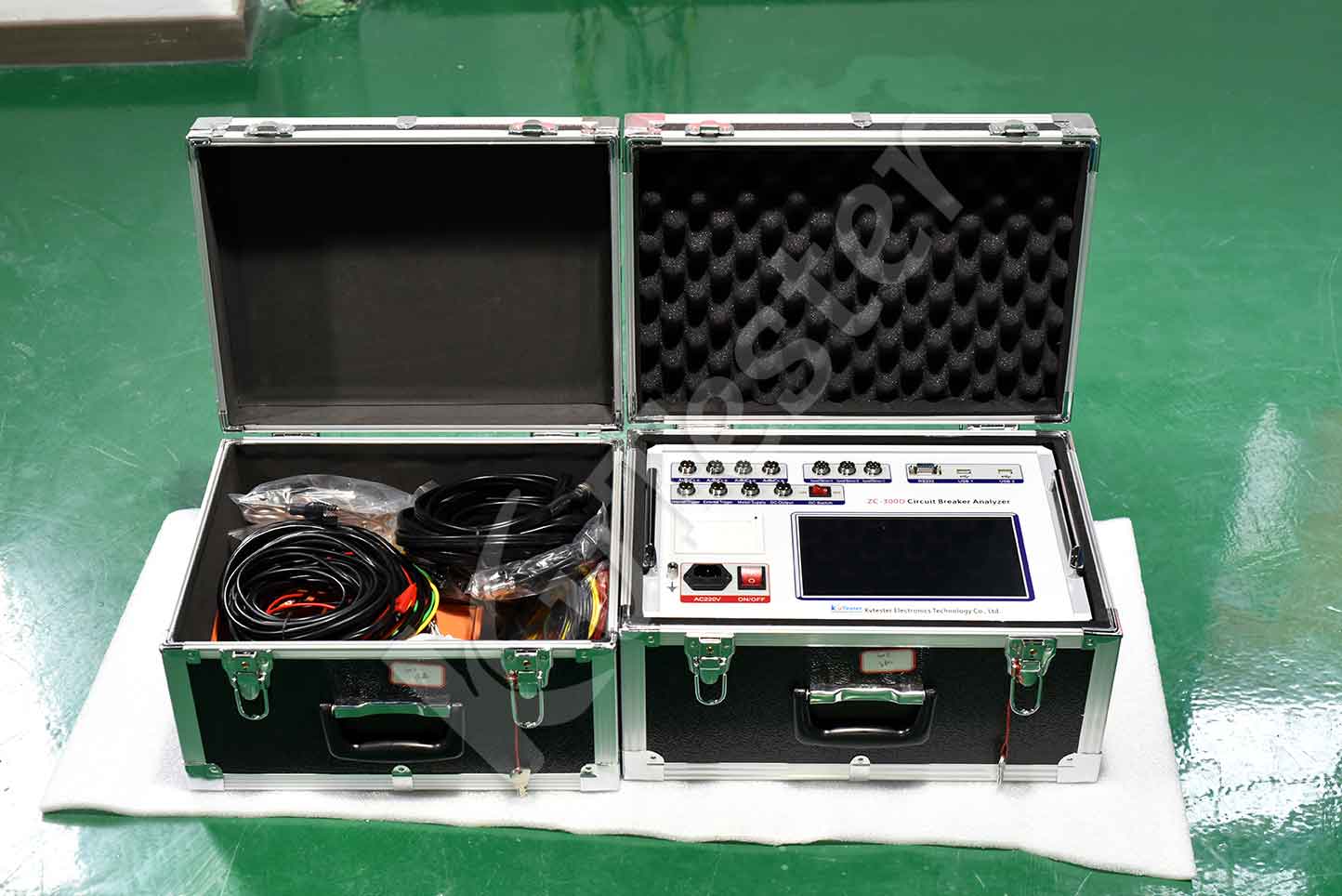
ZC-300C circuit breaker analyzer can be used to test and measure the mechanical characteristic parameters of high voltage switch ( such as vacuum, six fluoride, less oil, oil and other power systems. The measurement data is stable, strong anti-interference ability, can be in the 500KV level and below the power station to do experiments, wiring is convenient, simple operation, is the most convenient tool for high-voltage switch maintenance test.
Kvtester Electronics Technology Co.,Ltd. is a high-tech enterprise specializing in power testing, testing, research and development, production, and sales of testing equipment. It has been engaged in the electrical testing industry for many years, and its products are of high quality. We welcome customers to come and purchase. Service hotline: 0086-27-81778799, to learn more, visit the official website: www.kvtester.com


