Voltage transformer field tester is developed by high-end testing technology, large-scale electronic circuit design and in line with the relevant national regulations. It solves the problems of high working intensity and tedious operation in field verification of voltage transformer. At the same time, the product has reliable performance and powerful function.
Operation method
The actual secondary load of transformer directly affects whether the error of measuring transformer is qualified. In general, the secondary load of voltage transformer is required to be between 2.5VA and rated load; the secondary load of current transformer is required to be between 3.75VA and rated load, and cos φ = (0.8~1) is the load range meeting the requirements, otherwise the transformer operation error may be out of tolerance. Therefore, it is necessary to detect whether the secondary load of the transformer meets the requirements.
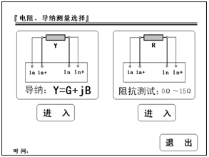
The following figure shows the selection interface of resistance and admittance test.
According to the different measuring objects, connect the tested objects and the instrument according to the wiring diagram displayed by the instrument, and then select admittance test or resistance test. (Note: please use the test lead provided by the manufacturer. 1a and 1a+ and 1x and 1x+ of the instrument are all short circuited at the test object end.)
1. Admittance test
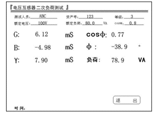
Enter this interface to test the voltage transformer load.
(1) Tester and asset number can be input.
(2) Grade: the level of load box is grade 3.
(3) Rated voltage: users can choose the secondary voltage of voltage transformer as 100 / 3V, 100/

V and 100V..
(4) Rated load: input the rated secondary load of the tested voltage transformer through the keyboard.
(5) Cos φ: power factor of input load.
(6) 246G: in phase component of admittance, conductance value, in mS.
(7) 2246246B: orthogonal component of admittance, admittance value, in mS.
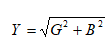
(8) Y: admittance value, in mS. The calculation formula is
(9) Cos φ: measure the actual power factor of the load.
(10) φ: measure the angle between the in-phase and orthogonal vector of the load.
(11) Load: the load value calculated according to the admittance value and the rated working voltage of the load, in VA.
Load = Un
2 x Y.
For example: Y = 60.0ms, rated voltage is 100/

V, then. Un
2 x Y = (100/

V)
2 x 60.0 x 10
-3 = 200.0(VA)
Note: for re-measurement, please exit the test interface and enter the interface again.


