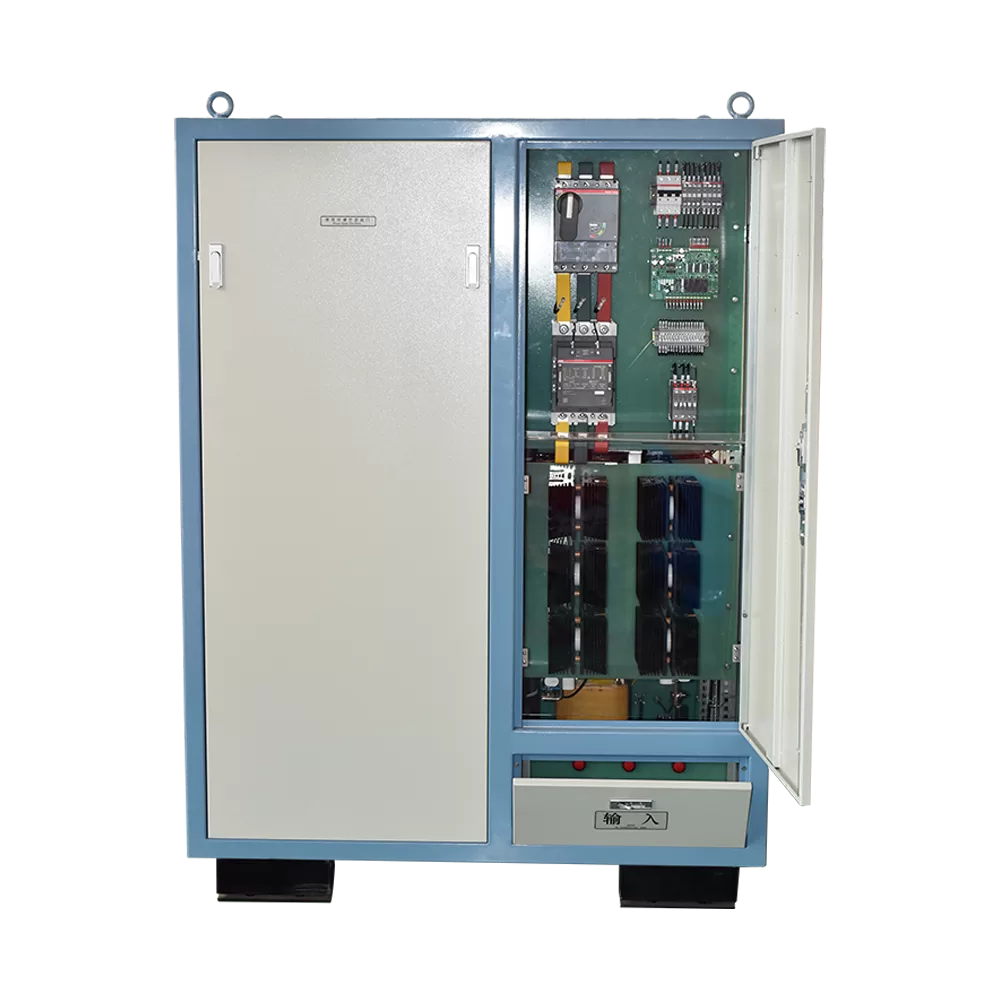
Features and Advantages
Applicable scenarios
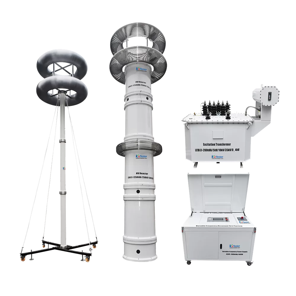
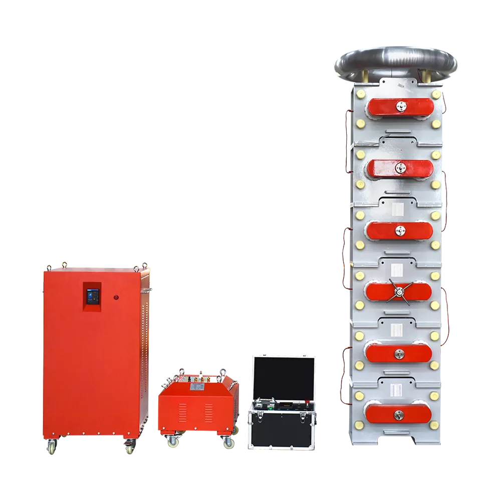
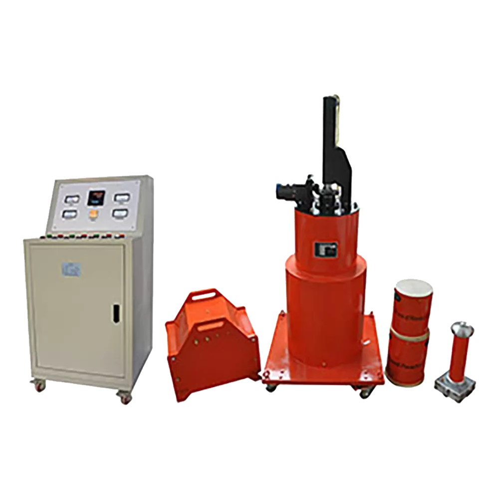
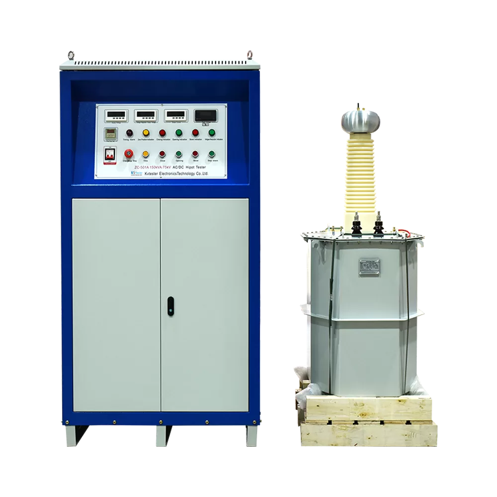
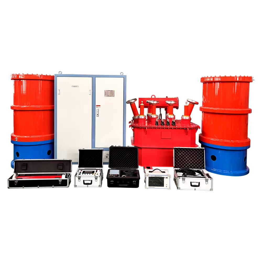
The non-partial discharge variable frequency power supply is the main component of the complete test system. The test system is suitable for:
1. Inductive withstand voltage and partial discharge test of power transformers.
2. AC withstand voltage and partial discharge test of mutual inductors, etc.
3. AC withstand voltage test of power cables.
4. AC withstand voltage test of GIS combined electrical appliances.
5. AC withstand voltage test of capacitive equipment such as circuit breakers, disconnectors, insulators, bushings, etc.
6. Suitable for power frequency withstand voltage test of large generator sets.
7. Suitable for power supply for large ground grid testing.
Features
1. The test has good equivalence. The output of this device is a sine wave with low waveform distortion. The waveform distortion rate is <3%, which is different from other types of variable frequency power supply devices (other types of variable frequency power supply devices are square wave outputs, which are sine waves formed by waveform shaping). Therefore, this device does not need to measure the peak value during the test.
2. It uses optical fiber control to completely isolate the high-voltage and low-voltage control circuits.
3. It is small in size, light in weight, flexible to carry, and very suitable for on-site use.
4. The operation is simple and convenient, the wiring is simple, and it can improve the work efficiency by 50% (relative to the generator set method).
5. It is safe and reliable. This device integrates a variety of protections. Including: discharge breakdown protection, overvoltage setting protection, output short circuit protection, startup zero position protection, bridge arm amplification circuit protection, power curve protection, etc. When any protection occurs, the device immediately disconnects the test voltage output and cuts off the main circuit power supply to ensure the safety of the test personnel, the test product and the test system.
6. The signal source in this device is generated by a dedicated chip and controlled by a microcomputer. The output frequency is highly stable and can reach 0.01Hz.
7. The variable frequency output voltage is controlled by TI’s high-speed microcomputer, and the output voltage instability is less than 1%.
Parameter
- System composition
- Main technical parameters of the system
- Technical parameters of non-partial discharge variable frequency power supply
- Technical parameters of non-partial discharge excitation transformer
- Technical parameters of the reactor without partial discharge compensation
- Technical parameters of non-partial discharge capacitor voltage divider
| System composition | |||
| Name | Specification Model | Quantity | Remarks |
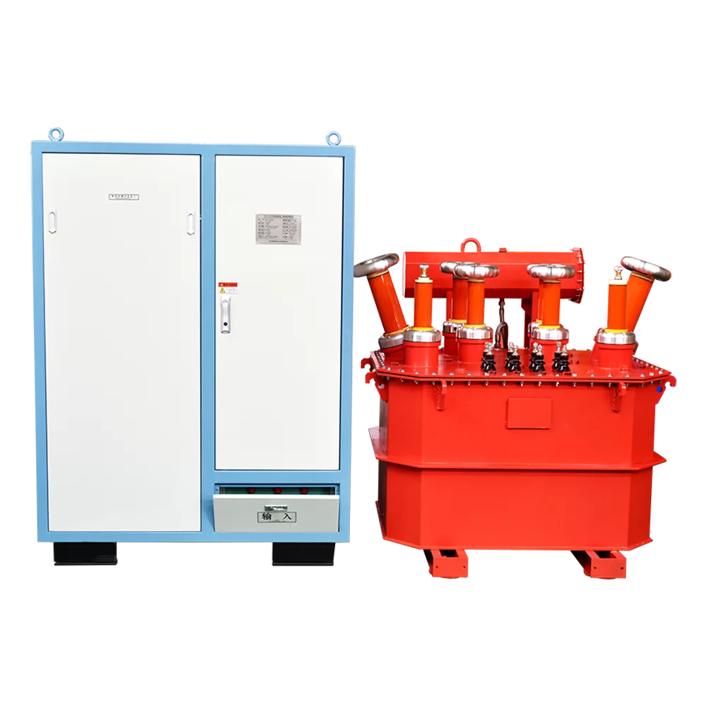
| No PD inverter power supply | WJF-150kW | 1 unit | |
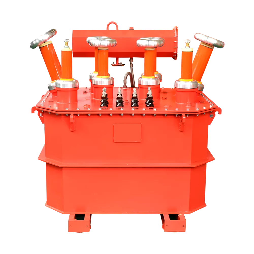
| No PD excitation transformer | JLB-150kVA/2×5kV; 2×15kV; 2×35kV/2×350V; 2×400V; 2×450V | 1 unit | |
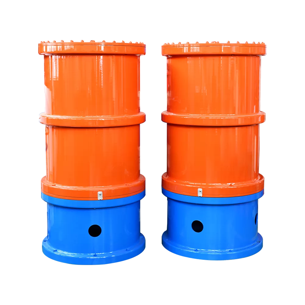
| No PD compensation reactor | DK-420kVA/35kV | 2 units | For PD test |
| No PD capacitor voltage divider | TRF-100kV/300pF | 1 unit | For PD test |
| Main technical parameters of the system | |
| Rated working input power | 380V±10% three-phase; 50Hz |
| Rated output power of variable frequency power supply | 150kW |
| Output phase number | single phase |
| Adjustable frequency range | 20Hz~400Hz, when the frequency is adjusted within the set range, the voltage is output at a constant level |
| Output frequency resolution | 0.01Hz |
| Output frequency instability | ≤0.1% |
| Output voltage waveform | sine wave |
| waveform distortion rate | ≤1.0% |
| System partial discharge | ≤10pC |
| System working time | The operating time during the transformer partial discharge test is 180min |
| Insulation level | Withstand voltage for 1min at 1.1 times the rated voltage |
| Technical parameters of non-partial discharge variable frequency power supply | |
| Rated input voltage | three-phase AC 380V±10%, 50Hz |
| Rated output power | single-phase 150kW |
| Output frequency range | 20Hz~300Hz, continuously adjustable |
| Rated output voltage | 0~350V, continuously adjustable |
| Rated output current | 0~428A, continuously adjustable |
| Frequency instability | ≤0.05% |
| Voltage instability | ≤1.0% |
| Nonlinear distortion | ≤1% |
| Partial discharge | ≤10pC (measured on the high-voltage side of the step-up transformer) |
| Working conditions | temperature -10℃~+45℃, humidity: 10-90%RH, altitude: ≤1000 meters |
| Cooling method | forced air cooling |
| Technical parameters of non-partial discharge excitation transformer | |
| Rated capacity | 250kVA |
| Low voltage winding rated voltage | 2×350V; 2×400V; 2×450V |
| High voltage winding rated voltage | 2×15kV, 2×40kV |
| High voltage winding rated current | 2×8.3A, 2×3.1A |
| Working frequency | 100~300Hz |
| Insulation level | low voltage winding to ground: 3kV/1min, high voltage winding to ground: 1.1 times inductive withstand voltage/1min |
| Partial discharge | partial discharge at rated voltage ≤10pC |
| Cooling method | ONAN |
| Allowed operating time | continuous operation at rated voltage and current for 90min |
| Technical parameters of the reactor without partial discharge compensation | |
| Rated voltage | 35kV |
| Rated current | 12A |
| Inductance | 9.3/5.4H (±2%) |
| Rated frequency range | 100~300Hz |
| Partial discharge at rated voltage | ≤10pC |
| Continuous working time | 90min continuous working at rated current |
| Temperature rise | winding temperature rise is less than 65K, top oil temperature rise is less than 55K |
| Insulation level | 1.1Un/1min |
| Technical parameters of non-partial discharge capacitor voltage divider | |
| Rated voltage | 100kV |
| Working frequency | 100~300Hz |
| Insulation level | 1.1Un/1min |
| Total capacitance | C1=500pF; C2=0.5μF. Structure: C1 is an epoxy cylinder shell oil-paper insulation structure capacitor; C2 uses the same material as C1 in temperature coefficient and frequency coefficient |
| System measurement error | ≤±1.0% |
| Dielectric loss | ≤0.5% |
| Dividing ratio | 1000:1 |
| Partial discharge amount | Partial discharge amount ≤10pC at rated voltage |