This product is developed by using modern electronic technology and tooling technology under the guidance of electromagnetic field theory, according to the field identification problems of multiple cables urgently needed to be solved by high-voltage cable construction and installation and maintenance personnel.
According to the market feedback and customer demand, the new generation ZC-701B live cable identification instrument is upgraded on the first generation of cable identification instrument, and frequency regulation function is added to adjust the speed of signal transmission to meet the field demand.
The wiring method of live cable identification instrument is divided into direct connection method and coupling method
A. The direct connection method is only applicable to the identification of non electrified cables.
B. The coupling method can be used to identify whether it is charged or not.
6.1 Disconnect the armor at both ends of the cable from the ground, clamp the red clip of the output line of the tester to be tested on the cable core (good phase or high insulation phase), clamp the black clamp of the output line of the tester on the grounding point or ground wire, and connect the corresponding core wire of the cable with the grounding point or grounding pile at the far end.
6.2 turn on the power switch of the identification instrument host.
Select output gear:
"I" is low grade, suitable for short cable;
"II" is high grade, suitable for long cable.
6.3 press the "start" button after confirming the cable status and wiring on site.
6.4 connect the recognizer receiver to the receiving clamp. Select "II" on the receiver;
6.5 note that the arrow direction of the receiving clamp is the current inflow direction (positive direction), otherwise the swing of the needle is opposite.
6.6 clamp the receiving clamp on the cable to be tested.
6.7 adjust the receiver sensitivity to the appropriate position,
6.8 at this time, the hand-held receiver can see the swing signal.
6.9 during the test, the "frequency adjustment" knob can be adjusted to select different signal frequencies according to the actual situation on site;
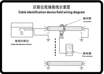
(Dead cable identification wiring) (Fig. 1)
After the transmitter and receiver start to work normally, the voltage induced in the test clamp is displayed on the handheld receiver, and the pointer swing direction is the signal direction. When the adjustment knob does not move, and the direction of the red arrow on the side of the test clamp is consistent with the cable direction, the receiver pointer deflects to the right and the swing amplitude is the cable to be found. All other cables have only return signals, and the pointer is deflected to the left and the swing is small.
Live cable identification instructions
(Note: select "I" on the receiver)
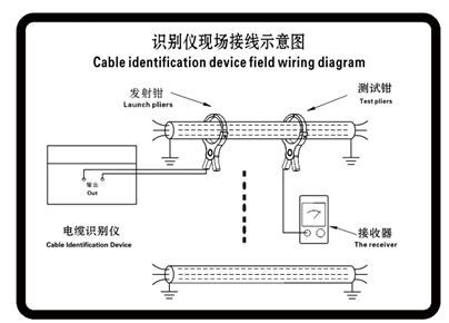
(Live cable identification wiring) (Fig. 2)
7.1. Turn on the power switch of the recognizer.
7.2. Clamp the transmitting clamp connected with the host of the identification instrument (the transmitting clamp shall be connected with the matching current limiting resistor in series) at the appropriate position of the live cable to be identified.
7.3. Press the "start" button after confirming the status and wiring of the on-site cable.
7.4. Connect the receiver of the live identification instrument with the receiving clamp, and select "I" position on the receiver
7.5. Clamp the receiving clamp on the cable to be tested.
7.6. Select "I" on the receiver, adjust the sensitivity of the receiver to a suitable position (gradually adjust from small to large, to prevent meter printing), and adjust the zero position of the meter head. At this time, only the live cable with signal can receive the signal, and the signal swing frequency is consistent with the switching frequency of the power output of the identification instrument.
7.7 in the case of strong interference, first adjust the sensitivity potentiometer to the lowest (rotate to the left). Zero adjustment should be repeated at the same time as the adjustment of sensitivity. In actual use, even the pointer should be adjusted to the left of "0" position. Repeatedly adjust the "zero adjustment" and "sensitivity" to gradually approach the maximum swing of the pointer. Comparing the amplitude, the largest amplitude is the cable to be identified.


