ZC-204B transformer short-circuit impedance tester has adjustable power output, which is especially suitable for measuring low-voltage short-circuit impedance of 110kV and above main transformers.
Connect the voltage regulator (using external power supply), the tester and the tested transformer according to the following wiring diagram. When using the external power supply, make sure that the voltage regulator is in the zero position before energizing the voltage regulator.
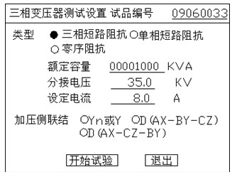
Figure 1 three phase transformer parameter setting interface
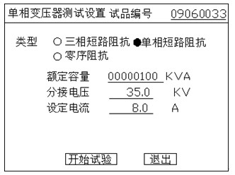
Figure 2 single phase transformer parameter setting interface
Select the three-phase transformer in the main interface to enter the three-phase transformer parameter setting interface in Figure 1, and select the single-phase transformer in the main interface to enter the parameter setting interface of single-phase transformer in Figure 2. The parameter significance of the parameter setting interface is as follows:
Test object number: the number of the tested transformer, which is printed out to facilitate record management; rated capacity: refers to the nominal capacity of the transformer;
Tap voltage: refers to the tap voltage of the pressurized winding;
Setting current: it refers to preparing to record the result at the current point. When the current is close to the setting current during the step-up test, the instrument will prompt
"Close to the set current", at the same time, the buzzer starts to alarm, at this time, the boost should be stopped.
Voltage side connection: the connection mode of voltage side of three-phase transformer, which is marked on the name plate of transformer.
Among them, the rated capacity and tap voltage must be set accurately. For three-phase transformer, the connection mode of the tested transformer must also be set correctly.
After the parameter setting is completed, press start test to enter the real-time measurement mode. Fig. 3 and Fig. 4 show the test measurement interface of three-phase transformer and single-phase transformer.
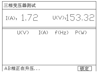
Figure 3 three phase transformer test interface
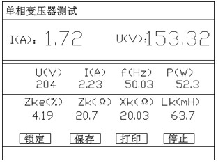
Figure 4 single phase transformer test interface
When using external power supply, the voltage regulator should be used to pressurize manually. The upper part of the test interface displays the current voltage and current value in real time. When the current is close to the set test current, the speed of voltage regulation should be slowed down. For single-phase transformer, when the preset current is reached, there will be an audio prompt and the current result will be automatically locked. The single-phase test result interface as shown in Fig. 4 will be displayed.
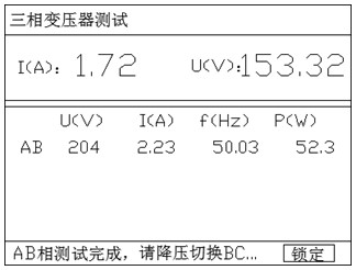
Figure 5 switching phase interface
For three-phase transformer, it is necessary to measure the AB, BC and Ca windings respectively and record the measurement results for three times. For example, when the AB phase result locking test is completed, the prompt of switching phase as shown in Figure 5 will be displayed. At this time, the voltage should be reduced, and then BC phase should be connected according to the wiring diagram, and the voltage rise test should be continued. The three measurements should make the applied current consistent as much as possible. In the third measurement, the instrument cannot be shut down or exit the three-phase test interface. At the bottom of the screen, the current instrument test phase is displayed. When the final test is completed, the measurement completion as shown in Figure 6 will be displayed
When the voltage drops to the safe voltage, the test result interface as shown in Figure 7 will be displayed automatically.
If the internal power supply is used to test single-phase or three-phase transformer, the instrument will automatically boost the voltage test, and then automatically cycle the test three times to display the test result interface as shown in Figure 5
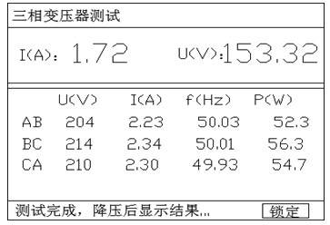
Figure 6 test completion interface prompt
After the three-phase measurement of the three-phase transformer is completed, the instrument automatically displays the calculated short-circuit impedance measurement results, as shown in Fig. 7.
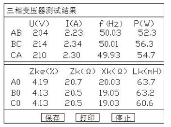
Figure 7 impedance test result interface
In the test result interface (see Figure 2 for single-phase results and see Figure 5 for three-phase results): U (V) is the recorded test voltage, unit V; I(A) Is the recorded test current in A; f (Hz) is the recorded test frequency in Hz; P (W) is the recorded measured power in W. Zke (%) is the percentage of short-circuit impedance voltage converted to rated current; Zk (Ω) is the short-circuit impedance of each phase, in Ω; Xk (Ω) is the reactance of each phase, in Ω; Lk (mH) is the leakage inductance of each phase, in mH.


