The turn to turn short circuit of rotor winding is a common fault of generator, but it is troublesome to deal with the fault. The turn to turn short circuit will not only affect the output, but also cause vibration. Therefore, attention should be paid to it. The AC impedance and loss test, DC resistance test, no-load and short-circuit test required in the "pre regulation" cannot be used as the final basis for formulating. According to the nature (static or dynamic) of inter turn short circuit, the induction electromotive force phase method and differential detection coil method can be used to determine.
1、 Purpose of AC impedance test of generator rotor
If there is a turn to turn short circuit in the rotor winding, the effective turns of the rotor winding will be reduced, and its AC impedance will be reduced, and the loss will be increased. Therefore, by measuring the AC impedance and power loss of the rotor winding, compared with the previous test data, we can effectively judge whether there is inter turn short circuit in the rotor winding.
2、 Test methods and precautions
1. Test method
Apply AC voltage to rotor winding and read voltage, current and power loss values.
The applied voltage is regulated by voltage regulator.
2. Precautions
(1) The values of impedance and power loss are determined by themselves. Under the same test conditions, there should be no significant change compared with the values over the years.
(2) The hidden pole rotor is measured out of bore or in bore and at different rotating speeds.
(3) Each test shall be conducted under the same conditions and voltage, and the peak value of test voltage shall not exceed the rated excitation voltage.
(4) After the rotor arrives at the site and before it is penetrated into the generator, the out of bore rotor AC impedance test shall be conducted, and the in bore test can be conducted after the rotor is penetrated into the generator. This project is a single test, which should be carried out by the installation unit.
(5) Before the whole set of unit starts, test instruments and wiring shall be prepared in advance. The unit in charge of the test shall be conducted by the commissioning unit and the installation unit through consultation.
(6) In the process of unit speed up, select different speed points to test until the unit constant speed of 3000 rpm.
(7) After the over speed test of the unit, the test shall be conducted again.
(8) During the test, attention should be paid to disconnect the excitation circuit. In order to avoid damage to the excitation circuit; due to the influence of excitation equipment, it cannot be pressurized.
(9) During the test, the external temporary power supply with sufficient capacity shall be selected, and the power switch with leakage protection shall not be used.
(10) Before the test, it should be confirmed that the carbon brush grinding meets the process requirements to avoid affecting the accuracy of the test data.
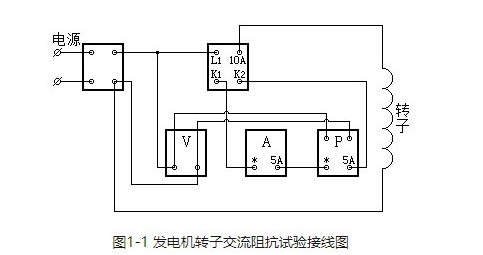
3、 Test wiring
If not, the following instruments can be used and connected according to Figure 1-1.
Instruments used: voltage regulator, standard CT, AC ammeter, AC voltmeter, active power meter.
Instrument selection: it is required to provide the data of AC impedance tester out of bore test, select AC voltmeter according to its applied voltage, and select standard CT, AC ammeter and active power meter according to test results.
4、 Judgment and report of test results
1. Judgment of test results
Under the same test conditions, there should be no significant change compared with the values over the years.
2. Data to be reflected in the test report
The contents of the report include: project name, test basis, instrument model, number, ambient temperature and humidity, test time, test location, equipment name, tester, test results, analysis and conclusion.


