Wireless secondary voltage drop load tester is also known as secondary voltage drop load on-line tester and transformer secondary voltage drop load online tester. A single host can complete the high-precision measurement of three-phase voltage, current, phase, frequency, power, power factor, three-phase imbalance and other electrical parameters. It has the advantages of small size, light weight, easy to carry, simple wiring and accurate test.
1. Measuring wiring
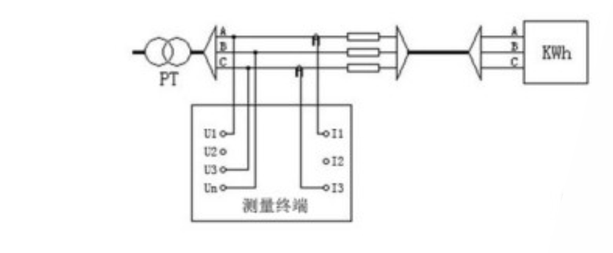
3-wire PT load test wiring
Test on PT side. The A, B and C phase voltage lines on PT side are respectively connected to U1, Un and U3 terminals of the measuring terminal; two clamp type current transformers A and C (respectively connected to I1 and I3 of the measuring terminal) are respectively connected to the A and C phases at the PT side. Note: the phases must be corresponding; otherwise the test results are incorrect. The wiring diagram is as follows:
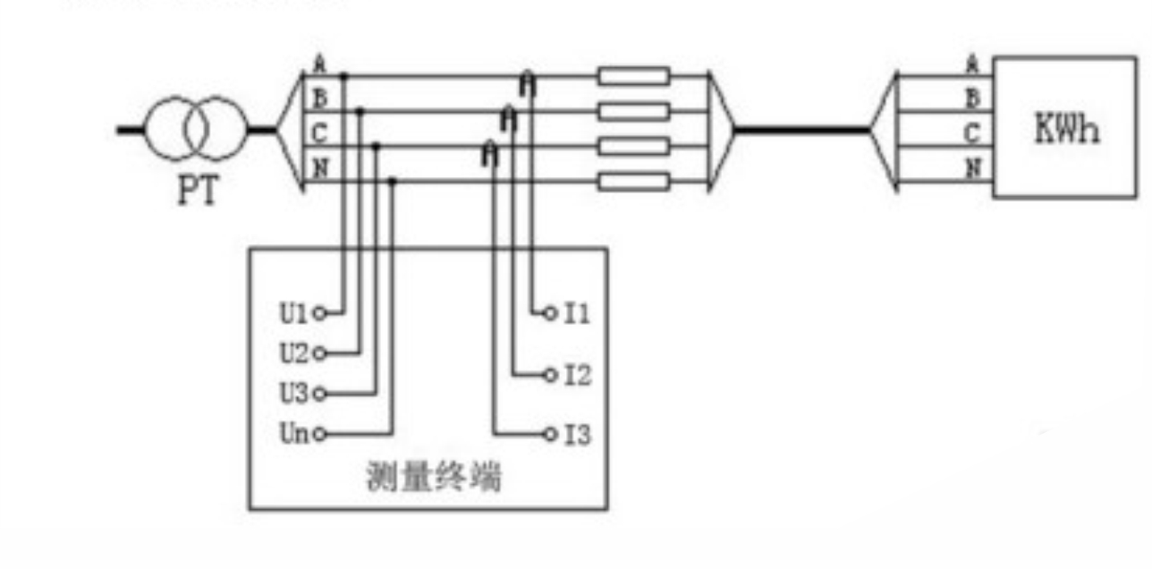
 4-wire PT load test wiring
Test at PT side, connect voltage lines of phase A, B, C and N on PT side to U1, U2, U3 and UN terminals of measurement terminal respectively; clamp three clamp current transformers to each phase of Pt side, and note: the phases must be corresponding, otherwise the test results are incorrect.
The wiring diagram is as follows:
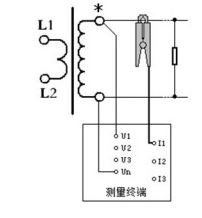
 CT load test wiring
The voltage is measured by A-phase voltage channel (connected to U1 and UN of the measuring terminal) and the current is measured by A-phase clamp current transformer (connected to I1 of the measuring terminal).
The wiring diagram is as follows:
2. PT secondary load test
Function description
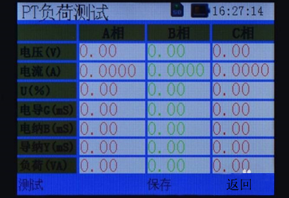
In the main interface, select "load test", press "ENTER" to enter the load test interface, then select "PT secondary load", press "ENTER", the interface is shown as follows:
This function is used to measure the secondary load of three-phase three wire Pt or three-phase four wire PT.
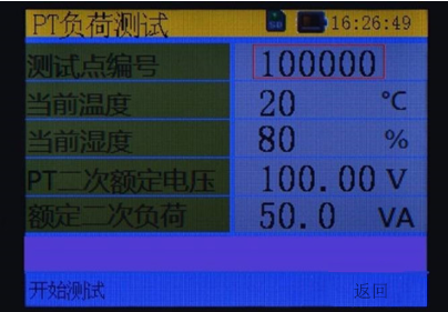
Before starting the test, it is necessary to set the test environment parameters, including the test point number, current temperature, current humidity, PT secondary rated voltage, rated secondary load. Move to the option to be changed by "←" and "→" keys, and then change with "↑" and "↓". After the change is completed, press F1 to enter the next interface, as shown in the following figure:
 Operating instructions
Start testing function
Operating instructions
Start testing function
Press the F1 key to start the test. The test results are displayed on the page, where u% represents the ratio of the actual voltage to the rated secondary voltage.
Save data function
Press the F3 key to save the current measurement results and the current measurement environment parameters to the internal memory.
Return to the test environment parameters interface
Press F4 to return to "PT load test parameter setting" interface.
Switch to the main interface
Press the menu key, the instrument will switch to the main interface.
3. CT secondary load measurement
Function description
In the main interface, select "load test", press "ENTER" to enter the load test interface, then select "CT secondary load", press "ENTER", the interface is shown as follows:
This function is used to test the secondary load of CT, and the interface is shown in the following figure:
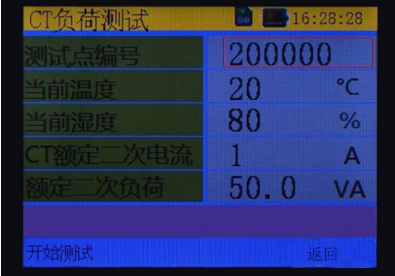
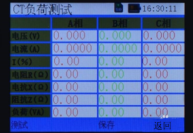
Before starting the test, it is necessary to set the test environment parameters, including test point number, current temperature, current humidity, CT secondary rated current and rated secondary load. Move to the option to be changed by "←" and "→", and then change it with "↑" and "↓". After the change is completed, press F1 to enter the next interface, as shown in the following figure:
 Operating instructions
Start testing function
Operating instructions
Start testing function
Press the F1 key to start the test. The test results are displayed on the page, where I% represents the ratio of the actual current to the rated secondary current.
Save data function
Press the F3 key to save the current measurement results and the current measurement environment parameters to the internal memory.
Return to the test environment parameters interface
Press F4 to return to "CT load test parameter setting" interface.
Switch to the main interface
Press the menu key, the instrument will switch to the main interface.


