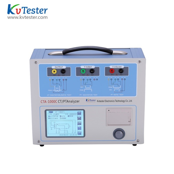
CTP-1000C transformer comprehensive tester is a new generation of new type CT and PT testing instrument, which is based on the traditional transformer volt ampere characteristic ratio polarity comprehensive tester based on voltage regulator, voltage booster and current transformer, after widely listening to users' opinions, after a lot of market research and in-depth theoretical research. The device adopts high-performance DSP and FPGA, and advanced manufacturing technology to ensure stable and reliable product performance, complete function, high degree of automation, high test efficiency and is in the leading level in China. It is a professional test instrument for transformer in power industry.
 Voltage transformer test
In the parameter interface, use the mouse to switch the cursor to the type column and select Pt as the transformer type.
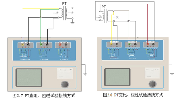
Test wiring
The test wiring steps are as follows:
Step 1: according to the description of PT test items described in Table 2.4, conduct wiring according to figure 2.7 or figure 2.8.
Figure 2.4 Description of PT test items
|
Resistance |
excitation |
transformation ratio |
description |
wiring diagram |
|
√ |
|
|
Measurement of PT secondary winding resistance |
Figure 2.7, the primary side must be disconnected |
|
√ |
√ |
|
Measurement of PT secondary winding resistance, excitation characteristics |
Figure 2.7, the primary side must be disconnected and the primary side high voltage tail must be grounded |
|
|
|
√ |
Check PT ratio and polarity |
Figure 2.8 |
Step 2: open circuit of other windings of the same PT.
Step 3: turn on the power and prepare for parameter setting.
Parameter setting
The test parameter setting interface of Pt is shown in Fig. 2.5.
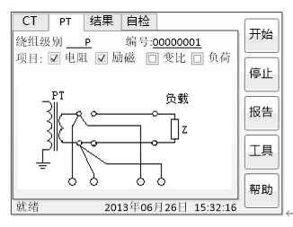
Figure 2.5 PT parameter setting interface
The parameter setting steps are as follows:
Rotate the mouse to switch the cursor and select the test item to be carried out. When the cursor stays at a certain test item, the screen displays the parameter settings related to the test item; when the cursor leaves the test item, the screen displays the wiring diagram corresponding to the selected test item.
The parameters that can be set are as follows:
(1) No.: input the test number.
(2) Rated secondary voltage: rated voltage at secondary side of voltage transformer.
(3) Level: the level of the measured winding, with two options, such as P and metering.
(4) Current temperature: the winding temperature during the test. Generally, the temperature at that time can be input.
(5) Rated frequency: optional values are: 50 Hz or 60 Hz.
(6) Maximum test voltage: the maximum power frequency equivalent voltage output by the equipment during the test.
(7) Maximum test current: the maximum AC current output by the equipment during the test.
Step 4: select the start button on the right to test.
Test result
The test results page is shown in Figure 2.6.
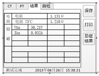
Figure 2.6 Test result interface of P-Level PT
For different levels of PT and selected test items, the test results are also different, as shown in table 2.5.
Table 2.5
|
test result |
Description |
P |
metering |
|
Resistance |
Resistance(25℃) R |
Unit: Ω, resistance at current temperature |
√ |
√ |
|
Resistance(75℃) R |
Unit: Ω, resistance value at reference temperature, temperature can be modified |
√ |
√ |
|
Excitation |
inflection point voltage and inflection point current |
Unit: Unit: V and a, respectively. According to the standard definition, when the inflection point voltage increases by 10%, the inflection point current increases by 5% |
√ |
√ |
|
Transformer ratio |
Transformer ratio |
Actual current ratio at rated load or actual load |
√ |
√ |
|
Turn ratio |
Actual turn ratio of secondary winding to primary winding under test |
√ |
√ |
|
Ratio difference, |
Current error between rated load or actual load |
√ |
√ |
|
phase difference, |
Phase difference under rated load or actual load |
√ |
√ |
|
polarity |
PT primary and secondary polarity relations, there are two kinds of polarity, namely, the same polarity/(reduced polarity) and reverse polarity/+(plus polarity) |
√ |
√ |


