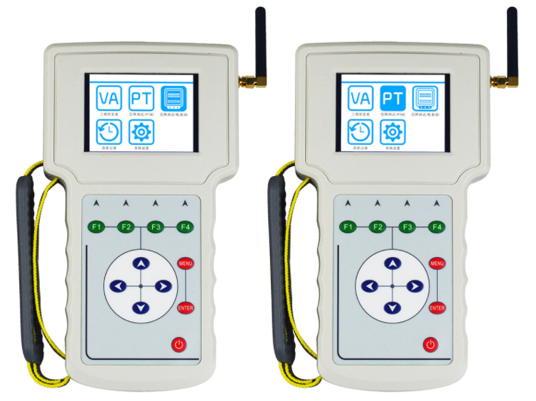
Zc-650 six phase protection loop vector tester developed by our company with the latest technology is also called wireless relay protection vector analyzer and loop vector analyzer. It is composed of two hand-held measuring terminals, which can measure six voltage, current amplitude and phase wirelessly and synchronously, and can also be used as a three-phase volt ampere phase meter separately
.
In order to make it more convenient for you to use, this paper introduces the technical specifications and measuring wiring points of zc-650 wireless relay protection vector analyzer.
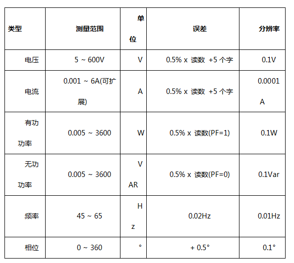
1、 Technical indicators
1. Measurement range and error
Note: wireless synchronous phase error: + 0.5 °; wireless communication distance: 1000m (open land); wireless repeater communication distance: 2000m (open land).
2. Working conditions
Working temperature: - 20 ~ 50 ℃, relative humidity: 0 ~ 95% non condensing
3. power supply
The built-in 3.7v/6000mah lithium battery can work continuously for up to 10 hours when the backlight is turned on (with the backlight off function turned on, the standby time is longer). It can also be powered by the 5V / 3A AC power adapter provided with the instrument.
2、 Measuring wiring
1. Y-type wiring
Clamp UN terminal (wire color is black) to the zero line of voltage signal to be measured. Clamp U1, U2 and U3 terminals (wire color is yellow, green and red) to a and B, C three phase line; if only one phase voltage needs to be measured, clamp UN terminal to the zero line and U1 terminal to the phase line to be measured; if two-phase voltage needs to be measured, clamp UN terminal to the zero line and U1 and U2 terminals to the phase to be measured.
The arrow on the side of the current clamp indicates the current direction. Clamp I1, I2 and I3 current clamps (the color circle on the clamp wire is yellow, green and red in turn) onto a, B and C three-phase phase wires; if only one current needs to be measured, clamp I1 current onto the current wire; if two current needs to be measured, clamp I1 and I2 current onto the current wire to be measured.
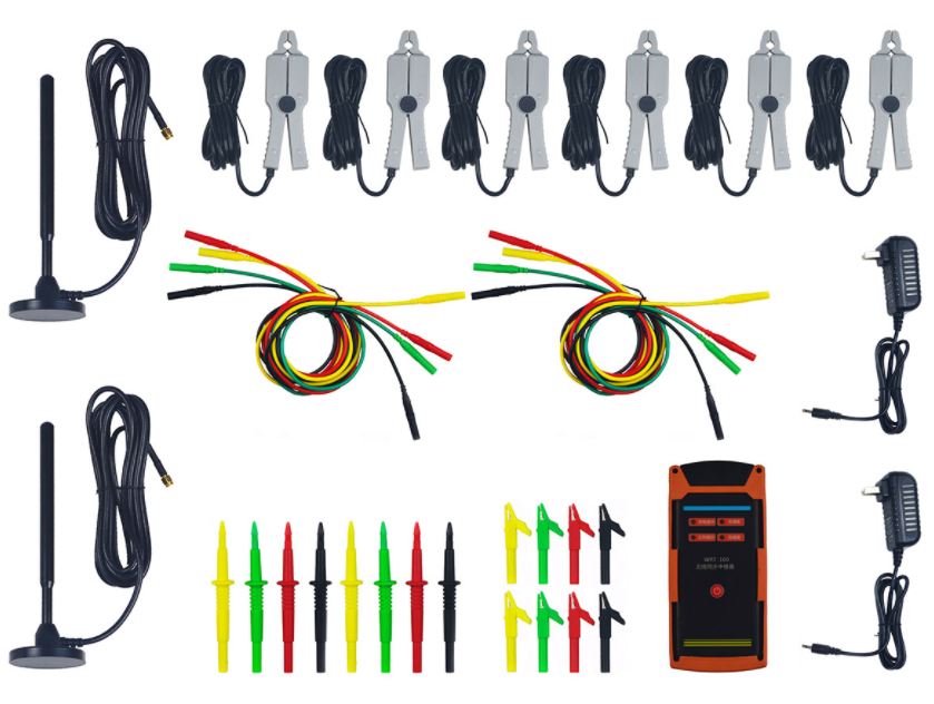
2. Delta type wiring
Clamp UN terminal (wire color is black) to phase B, U1 and U3 voltage terminal (wire color is yellow and red in sequence) to phase A and phase C. The arrow on the side of the current clamp indicates the current direction. Clamp I1, I2 and I3 current clamps (the color circle on the clamp wire is yellow, green and red in turn) onto a, B and C three-phase phase wires.
The above is the whole content of this paper. If you don't understand the wiring method of zc-650 six phase protection loop vector tester, you can consult our online customer service for details at any time